
Datasheet


For technical support and more information, visit http://power.ti.com
15-A, 5-V Input Non-Isolated
Wide-Output Adjust Power Module
SLTS204C – MAY 2003 – REVISED DECEMBER 2003
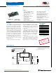
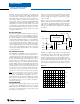
Standard Application
Features
• Up to 15-A Output Current
• 5-V Input Voltage
• Wide-Output Voltage Adjust
(0.8 V to 3.6 V)
• Efficiencies up to 96 %
• 160 W/in³ Power Density
• On/Off Inhibit
• Output Voltage Sense
• Pre-Bias Startup
• Margin Up/Down Controls
R
set
= Required to set the output voltage to a value
higher than 0.8 V. (See spec. table for values)
C
in
= Required 470 µF capacitor
C
out
= Optional 330 µF capactitor
• Auto-Track™ Sequencing
• Under-Voltage Lockout
• Output Over-Current Protection
(Non-Latching, Auto-Reset)
• Operating Temp: –40 to +85 °C
• Safety Agency Approvals:
UL 1950, CSA 22.2 950, EN60950
VDE (Pending)
• Point-of-Load Alliance (POLA)
Compatible
PTH05010
(Top View)
Margin Up
Margin Down
V
IN
L
O
A
D
C
IN
470 µF
(Required)
+
C
OUT
330 µF
(Optional)
+
Inhibit
GND
GND
V
OUT
V
o
Sense
Track
1
2
10 9 8
7
6
543
R
SET
(Required)
0.1 W, 1 %
Description
The PTH05010 series of non-isolated
power modules are small in size but big on
performance and flexibility. Their high
output current, compact footprint, and
industry-leading features offers system
designers a versatile module for powering
complex multi-processor digital systems.
The series employs double-sided surface
mount construction and provides high-
performance step-down power conversion
for up to 15 A of output current from a
5-V input bus voltage. The output volt-
age of the PTH05010W can be set to any
value over the range, 0.8 V to 3.6 V, using
a single resistor.
This series includes Auto-Track™.
Auto-Track simplifies the task of supply
voltage sequencing in a power system by
enabling modules to track each other, or
any external voltage, during power up and
power down.
Other operating features include an
on/off inhibit, output voltage adjust (trim),
and margin up/down controls. To ensure
tight load regulation, an output voltage
sense is also provided. A non-latching
over-current trip serves as load fault
protection.
Target applications include complex
multi-voltage, multi-processor systems
that incorporate the industry’s high-speed
DSPs, micro-processors and bus drivers.
Auto-Track™
Sequencing
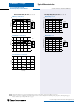
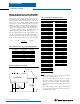
Pin Configuration
Pin Function
1 GND
2V
in
3 Inhibit *
4V
o
Adjust
5V
o
Sense
6V
out
7 GND
8 Track
9 Margin Down *
10 Margin Up *
* Denotes negative logic:
Open = Normal operation
Ground = Function active
NOMINAL SIZE = 1.37 in x 0.62 in
(34,8 mm x 15,75 mm)
PTH05010W —5-V Input