
Datasheet


"#$$$%
"#$$$%
SBVS001D − OCTOBER 1992 − REVISED JULY 2004
www.ti.com
10
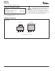
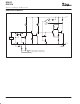
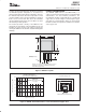
The SOT-223 package derives heat sinking from
conduction through its copper leads, especially the large
mounting tab. These must be soldered to a circuit board
with a substantial amount of copper remaining, as shown
in Figure 5. Circuit board traces connecting the tab and the
leads should be made as large as practical. The mounting
tab of both packages is electrically connected to V
OUT
.
Total Area: 50 x 50mm
35 x 17 mm
16 x 10 mm 16 x 10 mm
Without backside copper:
JA
≈
59
_
C/W
q
With solid backside copper:
JA
≈
49
_
C/W
q
Figure 5. SOT-223 Circuit Board Layout Example
Other nearby circuit traces, including those on the back
side of the circuit board, help conduct heat away from the
device, even though they may not be electrically
connected. Make all nearby copper traces as wide as
possible and leave only narrow gaps between traces.
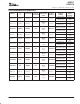
Table 1 shows approximate values of q
JA
for various circuit
board and copper areas for the SOT-223 package. Nearby
heat dissipating components, circuit board mounting
conditions, and ventilation can dramatically affect the
actual q
JA
. Proper heat sinking significantly increases the
maximum power dissipation at a given ambient
temperature, as shown in Figure 6.
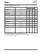
Table 1. SOT-223 q
JA
for Various Board
Configurations
(1)
SOT-223
THERMAL
TOTAL PC
BOARD
TOPSIDE
(1)
COPPER
BACKSIDE
COPPER
THERMAL
RESISTANCE
JUNCTION-
BOARD
AREA
COPPER
AREA
COPPER
AREA
JUNCTION-
TO-AMBIENT
2500mm
2
2500mm
2
2500mm
2
46°C/W
2500mm
2
1250mm
2
2500mm
2
47°C/W
2500mm
2
950mm
2
2500mm
2
49°C/W
2500mm
2
2500mm
2
0 51°C/W
2500mm
2
1800mm
2
0 53°C/W
1600mm
2
600mm
2
1600mm
2
55°C/W
2500mm
2
1250mm
2
0 58°C/W
2500mm
2
915mm
2
0 59°C/W
1600mm
2
600mm
2
0 67°C/W
900mm
2
340mm
2
900mm
2
72°C/W
900mm
2
340mm
2
0 85°C/W
(1)
Tab is attached to the topside copper.
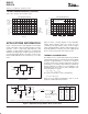
SOLDERING METHODS
Both REG1117 packages are suitable for infrared reflow
and vapor-phase reflow soldering techniques. The high
rate of temperature change that occurs with wave
soldering or hand soldering can damage the REG1117.
INSPEC Abstract Number: B91007604, C91012627.
Kelly, E.G. “Thermal Characteristics of Surface 5WK9Ω
Packages.” The Proceedings of SMTCON
. Surface Mount
Technology Conference and Exposition: Competitive
Surface Mount Technology, April 3−6, 1990, Atlantic City,
NJ, USA. Abstract Publisher: IC Manage, 1990, Chicago,
IL, USA.
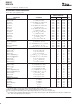
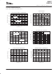
6
5
4
3
2
1
0
Power Dissipation (Watts)
0 255075100125
Ambient Temperature (
_
C)
MAXIMUM POWER DISSIPATION
vs AMBIENT TEMPERATURE
P
D
=(T
J
(max)
−
T
A
)/
JA
T
J
(max) = 150
_
C
q
DDPAK
SOT−223
JA
=85
_
C/W
(340mm
2
topside copper,
no backside copper)
q
JA
=46
_
C/W
(2500mm
2
topside and
backside copper)
q
JA
=27
_
C/W
(4in
2
one oz copper
mounting pad)
q
JA
=65
_
C/W
(no heat sink)
q
Figure 6. Maximum Power Dissipation versus Ambient Temperature