
Datasheet


"#$$$%
"#$$$%
SBVS001D − OCTOBER 1992 − REVISED JULY 2004
www.ti.com
2
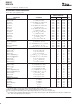
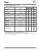
ABSOLUTE MAXIMUM RATINGS
(1)
Power Dissipation Internally Limited. . . . . . . . . . . . . . . . . . . . . . . . . .
Input Voltage +15V. . . . . . . . . . . . . . . . . . . . . . . . . . . . . . . . . . . . . . .
Operating Junction Temperature Range −40°C to +125°C. . . . . . . .
Storage Temperature Range −65°C to +150°C. . . . . . . . . . . . . . . . .
Lead Temperature (soldering, 10s)
(2)
+300°C. . . . . . . . . . . . . . . . .
(1)
Stresses above these ratings may cause permanent damage.
(2)
See Soldering Methods section.
This integrated circuit can be damaged by ESD. Texas
Instruments recommends that all integrated circuits be
handled with appropriate precautions. Failure to observe
proper handling and installation procedures can cause damage.
ESD damage can range from subtle performance degradation to
complete device failure. Precision integrated circuits may be more
susceptible to damage because very small parametric changes could
cause the device not to meet its published specifications.
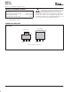
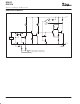
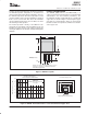
CONNECTION DIAGRAM
Front View
Plastic SOT−223
Plastic DDPAK
Tab is V
OUT
V
IN
V
OUT
Ground
(Adj.)
(1)
Tab is
V
OUT
V
IN
V
OUT
Ground
(Adj.)
(1)
NOTE: (1) Adjustable−Voltage Model.