
Datasheet


"#$$$%
"#$$$%
SBVS001D − OCTOBER 1992 − REVISED JULY 2004
www.ti.com
9
A simple experiment will determine whether the maximum
recommended junction temperature is exceeded in an
actual circuit board and mounting configuration: Increase
the ambient temperature above that expected in normal
operation until the device’s thermal shutdown is activated.
If this occurs at more than 40°C above the maximum
expected ambient temperature, then T
J
will be less than
125°C during normal operation.
The internal protection circuitry of the REG1117 was
designed to protect against overload conditions. It was not
intended to replace proper heat sinking. Continuously
running the REG1117 into thermal shutdown will degrade
reliability.
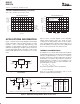
LAYOUT CONSIDERATIONS
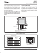
The DDPAK (REG1117F-3.3 and REG1117FA) is a
surface-mount power package that has excellent thermal
characteristics. For best thermal performance, the
mounting tab should be soldered directly to a circuit board
copper area, as shown in Figure 3. Increasing the copper
area improves heat dissipation. Figure 4 shows typical
thermal resistance from junction-to-ambient as a function
of the copper area.
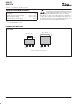
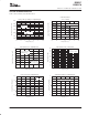
3−Lead DDPAK
(1)
NOTE: (1) For improved thermal performance increase
footprint area. See Figure 4 (Thermal Resistance vs
Circuit Board Copper Area).
All measurements
in inches.
0.45
0.085
0.2
0.51
0.10
0.155 0.05
Figure 3. DDPAK Footprint
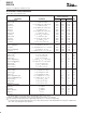
THERMAL RESISTANCE vs
CIRCUIT BOARD COPPER AREA
60
50
40
30
20
10
012345
Copper Area (inches
2
)
REG1117F
DDPAK Surface Mount Package
1oz copper
Thermal Resistance, q
JA
(°C/W)
Circuit Board Copper Area
REG1117F
DDPAK Surface−Mount Package
Figure 4. DDPAK Thermal Resistance versus Circuit Board Copper Area