FCC ID: A92S251B April ’00 Preface Series 2000 Reader System Reader S251B RI-STU-251B Reference Guide 11-06-21-054 April 2000 1
S2510 Reader - Reference Guide April ’00 Edition One - April 2000 This is the first edition of this manual, it describes the following equipment: TIRIS Reader S251B RI-STU-251B Texas Instruments (TI) reserves the right to make changes to its products or services or to discontinue any product or service at any time without notice. TI provides customer assistance in various technical areas, but does not have full access to data concerning the use and applications of customer's products.
PREFACE Read This First About This Guide This manual describes the TIRIS S251B Reader, its goal is to describe the reader, how it works, how to install it and how to use it. Regulatory, safety and warranty notices that must be followed are given in Chapter 5. Conventions WARNING: A WARNING IS USED WHERE CARE MUST BE TAKEN, OR A CERTAIN PROCEDURE MUST BE FOLLOWED IN ORDER TO PREVENT INJURY OR HARM TO YOUR HEALTH.
S2510 Reader - Reference Guide April ’00 Document Overview Page Chapter 1: Introduction . . . . . . . . . . . . . . . . . . . . . . . . . . . . . . . . . . . . . . . . . . . . 6 1.1 General............................................................................................... 7 1.2 System Description ............................................................................ 7 1.3 Product Description ............................................................................
April ’00 Preface List of Tables Page Table 1: List of Connectors .......................................................................... 11 Table 2: Power Range Settings ................................................................... 12 Table 3: Supply Connector........................................................................... 12 Table 4: Supply Connector - Specifications ................................................. 13 Table 5: General Purpose Inputs/Outputs..........................
CHAPTER 1 Introduction Chapter 1: Introduction This introduces you to the S251B Reader, what it is and what it does. Topic Page 1.1 General..........................................................................................................7 1.2 System Description......................................................................................7 1.3 Product Description.....................................................................................7 1.3.1 Interfaces ......................
April ’00 1.1 Chapter 1. Introduction General This document provides information about the S251B Reader. It describes the reader and how to install it. 1.2 System Description A TIRIS system comprises a reader connected to a control device (usually a host computer) via an RS232, or an RS422/RS485 interface, an antenna and a transponder. It is used for wireless identification of TIRIS LF transponders. The reader sends a 134.
S2510 Reader - Reference Guide 1.3.1 April ’00 Interfaces The reader has the following connections/interfaces: • Communications interface: RS232, RS422 or RS485 (F & G) • 8 general purpose I/O lines (B) • 2 Open Collector outputs (E) • Synchronization bus (C) • Carrier Phase Synchronization bus (D) • Power connector (A) • Indicator outputs connector (H) • Antenna connector (I) 1.3.2 Communications Protocols There are two protocols that can be used with the S251B Reader, they are: ASCII Protocol.
CHAPTER 2 Hardware Chapter 2:Hardware This chapter describes the hardware of the S251B Reader. It tells you which modules together comprise the reader. It also describes the front panel (switches connections etc.) and specifies the electrical inputs and outputs. Topic Page 2.1 General........................................................................................................10 2.2 Product Description...................................................................................10 2.2.
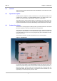
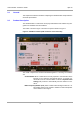
S2510 Reader - Reference Guide 2.1 April ’00 General This chapter describes the hardware comprising the S251B Reader and provides the electrical specifications. 2.2 Product Description The S251B Reader is contained in a IP20 polycarbonate box that enables easy integration into standard racks and cabinets. The reader is shown in Figure 1 and the front panel is shown in Figure 2. Figure 2: S251B Front Panel (with connector covers removed) The reader comprises two modules assembled together in a housing.
April ’00 2.2.1 Chapter 2. Hardware Connectors There are 10 connectors on the S251B, 7 WECO connectors, the antenna connector, a 9-pin sub-D RS232 connector, a 6-pin connector for the indicator outputs and a 2pin connector for the antenna. The function of each pin on each connector (except the RS232 sub-D connector) is described in the following paragraphs. Their location is shown in Figure 3.
S2510 Reader - Reference Guide April ’00 Table 1: List of Connectors 2.2.1.1 Identifying Letter Function Section F2 RS232 Connector 2.2.1.6 G RS422/RS485 Connector 2.2.1.7 H Indicator Outputs 2.2.1.8 I Antenna Connector 2.2.1.
April ’00 Chapter 2. Hardware Table 4: Supply Connector - Specifications 2.2.1.2 Parameter Minimum Maximum Logic Supply Voltage VSL 10 V 24 V Logic Supply current ISL - 2.5 A B - General Purpose Inputs/Outputs The Reader has eight general purpose TTL-Level Inputs/Outputs. By means of the configuration set-up, they can be set in groups of four to be Input or Output. Furthermore, there is a reset connection and a 5 V regulated output.
S2510 Reader - Reference Guide April ’00 Table 6: General Purpose Inputs/Outputs - Specifications 2.2.1.3 Parameter Minimum Maximum GP IO Output Voltage @ 6 mA Low level High level 3.15 V 0.9 V 5.
April ’00 Chapter 2. Hardware Table 8: Synchronization Interface - Specifications 2.2.1.4 Parameter Specification Receiver Input 12 kΩ Receiver Sensitivity ±200 mV Receiver Hysteresis 60 mV D - Carrier Phase Synchronization Interface The carrier phase synchronization interface is used to establish hard wired carrier phase synchronization with other readers through a single pair of wires. Its pin assignment is given in Table 9 and its specifications are given in Table 10.
S2510 Reader - Reference Guide 2.2.1.5 April ’00 E - Open Collector & I/Os This connector provide two open collector connections to and from the reader, plus the RXSS output (used to set the local noise level), another 5 V regulated output and an interrupt input. Its pin assignment is given in Table 11 and its specifications are given in Table 12.
April ’00 2.2.1.6 Chapter 2. Hardware F1 & F2 - RS232 Communication Interface Depending on the DIP-Switch configuration, the Reader will either communicate via the RS232, RS422 or RS485 interface. There are two interface connectors either of which can be used for an RS232C connection. They are: a standard RS232 Interface 9-pin SUB-D male connector (F1 on Figure 3) and a 6-pin WECO connector (F2 on Figure 3). Both of these connectors allow communication between the reader and a controlling device.
S2510 Reader - Reference Guide 2.2.1.7 April ’00 G - RS422/RS485 Communications Interface Depending on the DIP-Switch configuration, the Reader will communicate via the RS232, RS422 or RS485 interface. RS422/485 connections are made via the 6-pin WECO connector (G in Figure 3). Its pin assignment is given in Table 15 and its specifications are given in Table 16. Both, the ASCII and TIRIS Bus Protocol can be used with the RS422 interface.
April ’00 2.2.1.8 Chapter 2. Hardware H - Indicator Outputs This connector (H in Figure 3) is a 2 x 3-pin (double row) pin header connection which provides the LED output signals. Its pin assignment is given in Table 17 and its specifications are given in Table 18. Table 17: Indicator Outputs Pin Signal Description Direction 1 ACTIVE Open collector output: RF Module transmitter signal Output 2 VR270 Current limited output: (270 Ω in series to VCC) Output 3 O.K. Open collector output: O.K.
S2510 Reader - Reference Guide 2.2.2 April ’00 Switches There are three banks of DIP switches on the S251B Reader, one is for the Control Module set-up (12 switches), one is for the RS422/RS485/DAT settings (5 switches), and the third one is for the synchronization settings (5 switches). The Control Module set-up switches are listed in Table 21, the RS422/RS485/DAT settings are listed in Table 23, and the synchronization settings switches are listed in Table 24.
April ’00 Chapter 2. Hardware Figure 5: RS422/RS485/DAT Switches ON 1 Table 23: RS422/RS485/DAT Settings DIP Switches Switch OFF ON 1 RS422 RS485 2 RS422 RS485 3 - RS422/RS485 Rx+/Rxline-to-line termination (120 Ω) 4 DAT Disabled DAT Enabled 5 DAT LEDs Disabled DAT LEDs Enabled Notes: SW1 and SW2 must always be in the same position as each other, either both OFF or both ON.
S2510 Reader - Reference Guide 2.2.3 April ’00 Indicators There are six LEDs on the front panel of the reader they are described in Table 25. Table 25: Indicators Indicator Description EMI Indicates the presence of Electro Magnetic interference TX Active Indicates activation of the RF transmitter Read O.K. Indicates a response from a valid transponder Antenna Tuning L↑ Antenna out of tune, inductance too high O.K.
CHAPTER 3 Synchronization Chapter 3:Synchronization If you are using more than one reader in an application, it may mean that you need to synchronize their operation so that they do not interfere with each other. This chapter describes the various synchronization options. Topic Page 3.1 Introduction ................................................................................................24 3.2 Types of Synchronization .........................................................................24 3.
S2510 Reader - Reference Guide 3.1 April ’00 Introduction Where multiple readers are operating in the same area, it is necessary to coordinate the activities of those readers to avoid mutual interference. This is known as synchronization. Synchronization in this context means that the readers in your application are controlled in such a way that they do not interfere with each other.
April ’00 3.2.2 Chapter 3. Synchronization Wireless Synchronization Wireless synchronization can be used to control the coordination of readers, with standard antennas, provided the electrical noise in the environment is low for the type of antenna in use and the noise levels are constant. Wireless synchronization is only valid for charge-only reading of transponders.
S2510 Reader - Reference Guide 3.2.5 April ’00 Master/Slave Synchronization Master/Slave Synchronization is probably the most commonly used form of synchronization. One reader is configured to be the Master and this reader then controls all the other readers, which are configured as Slaves. There are three variants: Master/Slave Synchronization without Acknowledgement, Master/Slave Synchronization with Acknowledgement Triggered Synchronization. 3.2.5.1 M/S Synchronization without Acknowledgement.
April ’00 3.2.5.3 Chapter 3. Synchronization Triggered Synchronization Triggered Synchronization is a Master/Slave Synchronization Bus where there is just a pulse signal. All readers are configured as masters, but it is only one unit or a trigger pulse source that issues the synchronization pulse at suitable intervals for the required operations on the transponder.
S2510 Reader - Reference Guide April ’00 Figure 7: Distance between Antennas (top view) Table 27: Distances Between Antennas Antenna type Distance D1 [m] Distance D2 [m] RI_ANT_S02 <=> RI_ANT_S02 0.8 1.0 RI_ANT_G01 <=> RI_ANT_G01 1.7 1.5 RI_ANT_G02 <=> RI_ANT_G02 1.3 1.0 RI_ANT_G04 <=> RI_ANT_G04 2.0 1.
CHAPTER 4 Installation Chapter 4:Installation This chapter provides you with the information that you need to know in order to install the reader. This chapter also describes how to incorporate the various synchronization options. Topic Page 4.1 Introduction ................................................................................................30 4.2 General........................................................................................................30 4.3 Mechanical Mounting.........
S2510 Reader - Reference Guide 4.1 April ’00 Introduction Note: Always ensure that the reader is switched off when making or breaking connections to it. 4.2 General The S251B Reader has been designed with easy installation in mind. The following information provides you with any details such as switch settings and so on that you will need to know. 4.3 Mechanical Mounting a. If you are mounting the reader on a DIN rail TS35, clip the reader into the bottom of the rail and then snap it into the top.
April ’00 4.4 Chapter 4. Installation Communication Follow the instructions given in the section that describes the communications setup that you have decided to use in your system: Section 4.4.2 for RS232, Section 4.4.3 for RS422 and Section 4.4.4 for RS485. 4.4.1 Configuration CTL Setup switch 8 determines the mode of operation of the control module when power is applied to the control module.
S2510 Reader - Reference Guide April ’00 Table 28: RS232 9-pin Connector Pin Signal Description Direction 5 GND Signal Ground - 6 DSR Data Set Ready Output 7 - Not connected - 8 - Not connected - 9 - Not connected - Table 29: RS232 WECO Connector 4.4.2.
April ’00 Chapter 4. Installation Figure 8: Switch Settings for RS422 ON 1 Table 30: RS422/RS485 Connector 4.4.
S2510 Reader - Reference Guide 4.5 Synchronization 4.5.1 Software Controlled April ’00 There is no special wiring required for this type of synchronization. Make sure that you set the software configuration to No Sync. when you are configuring the reader. 4.5.2 Wireless Synchronization There are no switch or jumper settings for wireless synchronization. Make sure that you set the software configuration to wireless synchronization when you are configuring the reader. 4.5.
April ’00 4.5.4 Chapter 4. Installation Master/Slave (without acknowledgement) & Triggered Synch. Figure 11 shows the way that the Readers have to be connected for master/slave synchronization without acknowledgment; and triggered synchronization. Make sure that you set the software configuration to Master or Slave (according to Table 32 and Table 33) acknowledgement) when you are configuring the reader. Table 32 and Table 33 show the settings of the Line termination DIP switches.
S2510 Reader - Reference Guide 4.5.5 April ’00 Master/Slave (with acknowledgement) Figure 12 shows the way that the Readers have to be connected for master/slave synchronization with acknowledgement. Make sure that you set the software configuration to Master or Slave (according to Table 34) when you are configuring the reader. Table 34 shows the setting of DIP switch switches 1, 2 & 3.
April ’00 4.5.6 Chapter 4. Installation Transmitter Carrier Phase Synchronisation (CPS) To allow you to overcome the beat effect, the pulse width modulated oscillator signal is accessible at the CPS connector D. All readers to be driven by one oscillator must have their CPS connectors connected together as shown in Figure 13. DIP switch Synchronization-SW4 determines whether the internal oscillator or the external oscillator signal is used.
S2510 Reader - Reference Guide 4.6 April ’00 General Purpose Input/Outputs The S251B Reader has 8 connections that can be defined as either inputs or outputs (TTL level). These input/outputs must be configured in groups of 4 as shown in Table 35.
April ’00 4.7 Chapter 4. Installation LED Outputs The signals used for the indicator LEDs (Read O.K. and Transmitting) are available at Indicator Outputs connector (H), they can be used to drive external LEDs or buzzers, they must be connected as shown in Figure 14. Ensure that the values given Table 18 are not exceeded. Figure 14: Connecting the LED Outputs Reset The S251B Reader provides a connection for an external reset on pin 12 of the General Purpose Input / Output connector (B).
S2510 Reader - Reference Guide 4.9 April ’00 Antenna The S251B Reader can be used together with the TIRIS antennas RI-ANT-G01E, RIANT-G02E, RI-ANT-G04E and RI-ANT-S02C. If you wish to use it with your own design antenna that antenna must conform to the specifications given in Table 36. Note: The Stick Antenna (RI-ANT-S02C) must only be used together with a reader supply voltage up to 12 V.
CHAPTER 5 Warnings, Cautions and Notices Chapter 5: Warnings, Cautions and Notices This chapter provides the Warnings, Cautions and Notices that are relevant to the S251B reader. Topic Page 5.1 FCC/PTT Regulations ................................................................................42 5.2 Important note to Purchasers/Users of the S251B Reader in the U.S.A.42 5.3 WARNING....................................................................................................
S2510 Reader - Reference Guide 5.1 April ’00 FCC/PTT Regulations The TIRIS Reader RF produces emissions at 134.2 kHz. The radiation of the fundamental and the harmonics will vary with the type of antenna and other devices or functions connected to the Reader. Prior to operating the S251B Reader together with antenna(s) and power supply, the required FCC, PTT or relevant government agency approvals must be obtained.