S6500 Long Range Reader Module - Reference Guide May ’01 HF Reader System Series 6000 S6500 Long Range Reader Module RI-STU-650A Reference Guide 11-06-21-059 May 2001 1
S6500 Long Range Reader Module - Reference Guide May ’01 Edition One - May 2001 This is the first edition of this manual. It describes the following equipment: S6500 Long Range Reader Module RI-STU-650A Texas Instruments (TI) reserves the right to make changes to its products or services or to discontinue any product or service at any time without notice.
PREFACE Read This First About This Manual This reference guide for the S6500 Long Range Reader Module is designed for use by TI partners who are engineers experienced with Radio Frequency Identification Devices (RFID). Regulatory, safety and warranty notices that must be followed are given in Chapter 5. Conventions WARNING: A WARNING IS USED WHERE CARE MUST BE TAKEN, OR A CERTAIN PROCEDURE MUST BE FOLLOWED IN ORDER TO PREVENT INJURY OR HARM TO YOUR HEALTH.
S6500 Long Range Reader Module - Reference Guide May ’01 Document Overview Chapter 1: Page Introduction. . . . . . . . . . . . . . . . . . . . . . . . . . . . . . . . . . . . . . . . . . . . . . . . . . . . . . . . . . . . 6 1.1 General .................................................................................................................... 7 1.2 System Description .................................................................................................. 7 1.3 Product Description .....
May ‘01 Preface List of Tables Page Table 1: List of Connectors............................................................................................... 11 Table 2: Antenna Connectors........................................................................................... 11 Table 3: Antenna - Specifications..................................................................................... 11 Table 4: Supply Connector ..............................................................................
CHAPTER 1 Introduction Chapter 1:Introduction This chapter introduces you to the S6500 Long Range Reader Module. Topic Page 1.1 General........................................................................................................7 1.2 System Description....................................................................................7 1.3 Product Description...................................................................................7 1.4 Communications Protocols ...............
May ’01 1.1 Chapter 1. Introduction General This document provides information about the S6500 Long Range Reader Module. It describes the reader and how to install it. 1.2 System Description The HF Reader System Series 6000 works at a frequency of 13.56 MHz. It comprises a reader, antenna and transponder (for example: smart label) and is used for wireless identification of a variety of objects.
May ’01 1.1 Chapter 1. Introduction General This document provides information about the S6500 Long Range Reader Module. It describes the reader and how to install it. 1.2 System Description The HF Reader System Series 6000 works at a frequency of 13.56 MHz. It comprises a reader, antenna and transponder (for example: smart label) and is used for wireless identification of a variety of objects.
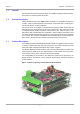
S6500 Long Range Reader Module - Reference Guide 2.1 May ’01 General This chapter provides a description of the S6500 Long Range Reader Module hardware. It also provides the electrical specifications of the inputs and outputs. Mechanical Information Figure 2 shows the location of the connectors, jumpers and LEDs on the S6500 Reader.
May ’01 2.3 Chapter 2. Reader Hardware Connectors Three connectors are located on the lower pcb and 5 connectors are on the upper pcb. The connectors are all shown on Figure 2. Table 1 provides an overview of all the connectors and lists the section that describes them. Table 1: List of Connectors 2.3.1 Identifying Letter Function Section X1 Rx Only Antenna Connection 2.3.1 X2 Tx/Rx Antenna Connection 2.3.1 X3 Voltage Supply 2.3.2 X6 Isolated Optocoupler Outputs 2.3.
S6500 Long Range Reader Module - Reference Guide 2.3.2 May ’01 Supply Connector (X3) The supply voltage is connected to connector X3 on the lower circuit board. Table 4: Supply Connector Pin Name Description 1 + 24 V Positive supply 2 GND Ground Table 5: Supply Connector - Specifications 2.3.3 Parameter Minimum Maximum Logic Supply Voltage VSL 23.75 V 25.2 V Logic Supply current ISL - 2.
S6500 Long Range Reader Module - Reference Guide 2.3.6 May ’01 RS485 Interface (X9) Depending on the configuration, the reader module will communicate either via the RS232 or RS485 interface (see Section 3.5). The RS485 interface is connected to X9. The transmission parameters can be software configured. Table 12: RS485 Interface Connector Pin Name Description Direction 1 Rx+/Tx+ RS485 Non-inverted data Input/Output 2 Rx+/Tx+ RS485 Inverted data Input/Output 3 GND Signal ground - 4 - n.
May ’01 2.4 Chapter 2. Reader Hardware Reader Module LEDs There are five (one green and four red) LEDs on the reader. Their location is shown in Figure 2 and their function is described in Table 14. Table 14: Description of LEDs Name Description LED V1 (green) “RUN-LED” - If all checks are OK this LED comes on (flashes) when V5 goes out. It indicates that the reader’s internal software is running properly. - Flashing rate approximately 1 Hz.
S6500 Long Range Reader Module - Reference Guide 2.5 May ’01 Switches There are two switches on the reader. Their location is shown in Figure 2 and their function is described in Table 15. Table 15: Description of Switches Name Description S1 Reset button S2 1 - Setting data bus addresses (0 ... 7) 2 - Setting data bus addresses (0 ... 7) 3 - Setting data bus addresses (0 ...
S6500 Long Range Reader Module - Reference Guide 3.1 May ’01 Introduction Note: Always ensure that the reader is switched off when making or breaking connections to it. 3.2 General The S6500 Reader Module has been designed with easy installation in mind. The following information provides you with any details that you will need to know. 3.2.
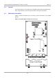
May ’01 Chapter 3. Installation Note: Detuning of the antenna can result in additional heat being generated in the reader. If this happens the reader regulates its output power down until the final stage is once again within its upper temperature limit. Figure 3: Reader Mounting Holes 120 mm 110 mm ø 4,5 mm ø 4,5 mm The tolerances for the position of the mounting holes is ± 0.5 mm.
S6500 Long Range Reader Module - Reference Guide 3.4 3.4.1 May ’01 Connectors Power Supply Connector The supply voltage is connected to connector X3 on the lower circuit board. CAUTIONS: 1. Reversing the power supply wires may destroy the device. 2. If you are using a switched power supply you must ensure that the switching frequency is below 300 kHz. Figure 4: Supply Voltage Connector X3 X3 1 2 +24 V DC GND ! X1 Notes: 1.
May ’01 Chapter 3. Installation Figure 5: Antenna Line on a Ring Core 3.4.3 Isolated Optocouplers Input Connector The input LED's on the optocouplers have an internal input series resistor of 500 Ω. For supply voltages above 10V the input current must be limited to a maximum of 20 mA by an additional external dropping resistor (see Figure 6 and Table 16). CAUTION: Reversing the polarity or overloading the inputs will destroy the reader. Notes: 1.
S6500 Long Range Reader Module - Reference Guide 3.4.4 May ’01 Isolated Optocoupler Outputs Connector The transistor connections, collector and emitter, of the two optocoupler outputs are galvanically isolated from the reader electronics and brought out on connector X6 without any additional circuitry. The outputs must therefore be powered by external supplies. The outputs are designed to switch resistive loads only. Note: If the connecting cable is longer than 3 m you must use shielded cable.
May ’01 3.4.5 Chapter 3. Installation Relay Connector CAUTIONS: The two relay change-over contacts are designed to switch resistive loads only. If you are using an inductive load, the relay contacts must be protected by means of an external protection circuit. Figure 8: Relay Connector X11 common normally closed normally open 3.4.6 1 2 3 RS485 Connection Figure 9: RS485 Interface X9 1 2 3 4 5 6 3.4.7 Tx+/Rx+ Tx-/Rx GND n.c. n.c. n.c.
S6500 Long Range Reader Module - Reference Guide May ’01 Figure 11: RS232 Interface Line on a Ring Core 3.5 Interface Configuration Jumper Settings There are five jumpers used on the reader. They are Jumpers J400 - J401 which are used to configure the asynchronous interface for RS232 or RS485 described in Table 17, and Jumpers J403, J405 and J407 are used to insert the termination resistors which may be required for the RS485 interface, described in Table 18 and shown in Figure 14.
May ’01 Chapter 3. Installation Figure 14: Jumper Settings for RS485 Line Termination J405 RS485 - B+ J403 J407 3.6 RS485 - A- Setting Bus Addresses If you are going to use the reader connected to a bus you will have to give each reader an individual address. You can do that either by setting switch S2 on the reader or by software from the controlling computer. 3.6.1 Using S2 to Set the Address You can use switch S2 to set the reader address between “0" and “7".
CHAPTER 4 Technical Data Chapter 4:Technical Data This chapter provides the technical specifications of the S6500 Reader Module. It also provides information about packing and storage. Topic Page 4.1 Specification Summary ...........................................................................27 4.2 Mechanical Information ...........................................................................
May ’01 4.1 Chapter 4. Technical Data Specification Summary Table 19: Ambient Conditions Operating Temperature -20°C to +65°C Storage Temperature -40°C to +85°C Vibration According to EN60068-2-6, 10 Hz to 200 Hz: 0.15 mm / 2 g Shock According to EN60068-2-27, acceleration 30 g Table 20: Electrical Data Supply Voltage 24 VDC +5%/-1% Ripple: maximum 20 mV Power Consumption maximum 60 W Operating Frequency 13.56 MHz ± 7 kHz Transmitter Power 0.5 to 10 W* (set by software in steps of 0.
S6500 Long Range Reader Module - Reference Guide Mechanical Information • Dimensions (W x L x H) 120 x 160 x 69 mm • Weight 650 g Figure 15 shows the dimensions of the S6500 Reader. The tolerances are: Length and Width: ± 0.5 mm Height: ± 2.0 mm 6 mm 43 mm 69 mm Figure 15: Reader Dimensions and Mounting Holes 120 mm 110 mm ø 4,5 mm 28 160,00 mm 150,00 mm ø 4,5 mm ø 4,5 mm 100 mm ø 4,5 mm 4.
CHAPTER 5 Regulatory, Safety and Warranty Notices Chapter 5:Regulatory, Safety and Warranty Notices This chapter provides important information about regulatory constraints and safety precautions. Topic 5.1 Page Regulatory Notes .....................................................................................30 5.1.1 FCC Notices (U.S.A.) ...........................................................................30 5.1.2 R&TTE Conformity (Europe) ......................................................
S6500 Long Range Reader Module - Reference Guide 5.1 May ’01 Regulatory Notes An RFID system comprises an RF transmission device, and is therefore subject to national and international regulations. Prior to operating the S6500 Long Range Reader Module together with antenna(s) and power supply, the required FCC, PTT or relevant government agency approval must be obtained. Sale, lease or operation in some countries may be subject to prior approval by the government or other organization. 5.1.
May ’01 5.2 5.2.1 Chapter 5. Regulatory, Safety and Warranty Notices Safety Precautions Human Safety WARNING: CUSTOMERS USING THE S6500 READER MODULE ARE RESPONSIBLE FOR OPERATING THEIR SYSTEM UNDER IMPLEMENTED POWER LEVELS AND ANTENNA CONFIGURATIONS AGAINST RELEVANT STANDARDS FOR HUMAN SAFETY IN ELECTRONIC FIELDS. 5.2.
APPENDIX A Terms & Abbreviations The terms and abbreviations used in this manual can be found in the TIRIS Terms and Abbreviations Manual - document number 11-03-21-002. This manual can be found in the document center on our home page: http://www.ti-rfid.