
Weather Radio User Manual
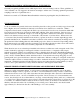

Step 2: Attach wind vane and counter-weight to the direction sensor head.
Loosen the two set screws on the top of the wind vane (upper unit).
Insert the vane and counter-weight into the holes. Be sure to press both parts all the way in and
make sure the flat areas on each arm face the set-screws.
Tighten the set screws.
Note: For optimum performance and maximum bearing longevity you may wish to fine-tune the
balance of both wind sensors. Place the U-tube flat on a table such that the sensors hang over the
edge. Rotate the vane and the cup in 10 degree increments. After positioning the vane and cups
verify that there is no movement after releasing your hold (this must be done in a wind-free
environment). Balance adjustments are made by loosening the set screw to the lighter cup,
counter-weight or fin and shifting it slightly away from the sensor head.
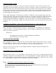
Step 3: Attach cross-bar to U-tube.
Spread end clamps and slide over the U-tube.
Insert cross-bar into the ends of both clamps.
Fasten cross-bar in a level position with screws, nuts and washers.
Step 4: Attach U-bolts to cross-bar and U-tube.
Remove the two nuts and reinforcing plate from both U-bolts (do not remove the toothed bracket).
Insert one U-bolt through the two holes in the cross-bar and the other through the two holes in the
bottom of the U-arm (be careful not to damage the wires inside the U-arm).
Replace the tube reinforcing plate on the U-bolt and replace the U-bolt nuts.
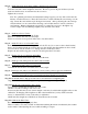
Step 5: Slip the U-bolts over the mast and tighten.
Make certain that the anemometer cups do not hit the mast.
Step 6: Attach guy wire clamp just below the U-tube assembly.
Step 7: Attach base mount to the roof or side wall.
Note that the base mount U-bolt will rotate to fit any angle.
Step 8: Install guy wire anchors (not included) or locate secure points for guy wire attachment.
Step 9: Erect mast and install guy wires (not included) and turn-buckles (not-included).
Step 10: Ground the mast to help protect the sensors and structure from lightning hits.
Supplies needed: mast wire clamp, grounding wire, wire supports and grounding rod.
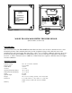
Step 11: Run the sensor wire inside to the console.
Lead in wire is permanently attached to the sensor unit.
Attach to console according to wire color code.
If necessary the cable may be cut down in length or wire may be added with negligible effect on the
calibration. If changing cable lengths more than a few hundred feet you may wish contact the
factory to determine the severity of the effect on calibration.
Additional cable lengths are available from Texas Electronics if needed.
Step 12: Calibrate the Wind Vane.
Be sure console is operating properly first.
This is normally a two man job with one individual watching the direction indicated by the weather
station and the other adjusting the sensor while watching a compass.