
User's Guide Power Amplifier SLOU082


Using The TPA032D03 Class-D EVM Stand-Alone
3-8
Details
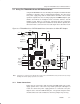
3.7.2 Input Connections
The class-D amplifier input signals can be connected in either of two ways:
differential or single-ended. For differential operation, connect the signal
source to the positive and negative inputs (IN+ and IN– module pins). For
single-ended operation, the input signal line should be connected to the IN+
module pin and the signal source ground wire should be connected to the
IN– module pin.
The EVM headphone amplifier inputs are single-ended, and the signal source
should be connected to the RHP and LHP module pins. For best results, the
ground of the signal source should be connected to the module GND pins at
the EVM headphone inputs to provide a return path for the current.
The input signal and ground wires should be twisted to reduce inductance and
noise pickup if the lead lengths are long and the cable is not shielded.
3.7.3 Output Connections
The speaker should be connected between the OUT+ and the OUT– module
pins. Inserting a plug into the EVM headphone jack switches the EVM to the
headphone mode and shuts down the class-D amplifier section.
3.7.4 Controls and Indicators
The mute, mode, and shutdown functions may be controlled externally via the
module Mute, Mode, and SD pins. An active-low input to the module Mute pin
mutes the selected amplifier. An active-low input to the module Mode pin
switches the EVM to the class-D mode and shuts off the headphone amplifier.
An active-low input to the module SD pin shuts down the device. A signal of
2 V or higher, allows normal operation.
Note that the mute, mode, and shutdown signals applied to the EVM control
input pins must be able to supply enough current to overcome the pullup
resistor on the module (100 kΩ).
The fault indicator circuit can be monitored at FAULT0 (TP1) and FAULT1
(TP2). These are open-drain outputs with 100-kΩ resistors connected to VDD
(5 V). A fault table is shown in Section 3.2.1 and in the device data sheet.