
Car Stereo System - Car Radio Digital Signal Processor User Manual

www.ti.com
7.7 PLL1 and PLL1 Controller
SM320C6455-EP
FIXED-POINT DIGITAL SIGNAL PROCESSOR
SPRS462B – SEPTEMBER 2007 – REVISED JANUARY 2008
The primary PLL controller generates the input clock to the C64x+ megamodule (including the CPU) as
well as most of the system peripherals such as the multichannel buffered serial ports (McBSPs) and the
external memory interface (EMIF).
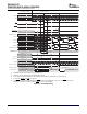
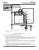
As shown in Figure 7-10 , the PLL1 controller features a software-programmable PLL multiplier controller
(PLLM) and five dividers (PREDIV, D2, D3, D4, and D5). The PLL1 controller uses the device input clock
CLKIN1 to generate a system reference clock (SYSREFCLK) and four system clocks (SYSCLK2,
SYSCLK3, SYSCLK4, and SYSCLK5).
PLL1 power is supplied externally via the PLL1 power-supply pin (PLLV1). An external EMI filter circuit
must be added to PLLV1, as shown in Figure 7-10 . The 1.8-V supply of the EMI filter must be from the
same 1.8-V power plane supplying the I/O power-supply pin, DV
DD18
. TI requires EMI filter manufacturer
Murata, part number NFM18CC222R1C3 or NFM18CC223R1C3.
All PLL external components (C1, C2, and the EMI Filter) must be placed as close to the C64x+ DSP
device as possible. For the best performance, TI recommends that all the PLL external components be on
a single side of the board without jumpers, switches, or components other than the ones shown. For
reduced PLL jitter, maximize the spacing between switching signals and the PLL external components
(C1, C2, and the EMI Filter).
The minimum CLKIN1 rise and fall times should also be observed. For the input clock timing
requirements, see Section 7.7.4 , PLL1 Controller Input and Output Clock Electrical Data/Timing.
CAUTION
The PLL controller module as described in the TMS320C645x DSP
Software-Programmable Phase-Locked Loop (PLL) Controller User's Guide (literature
number SPRUE56 ) includes a superset of features, some of which are not supported
on the C6455 DSP. The following sections describe the features that are supported; it
should be assumed that any feature not included in these sections is not supported
by the C6455 DSP.
C64x+ Peripheral Information and Electrical Specifications136 Submit Documentation Feedback