
Datasheet

SN105125
150-mA LOW DROPOUT REGULATOR WITH POK
SLVS418 – JANUARY 2002
10
POST OFFICE BOX 655303 • DALLAS, TEXAS 75265
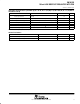
THERMAL INFORMATION
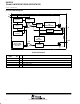
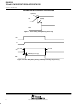
The SN105125 is designed to provide a continuous load current of 150 mA when the maximum power
dissipation of the package is not exceeded in the application. To determine the maximum power dissipation of
the package, use the junction-to-ambient thermal resistance of the device. The basic equation is as follows:
Maximum power dissipation (W)
P
D(MAX)
= (T
J(MAX)
– T
A
) / R
θJA
(maximum power dissipation limit)
Where:
T
J(MAX)
is the maximum junction temperature of the die (less than 150°C, minimum thermal shutdown)
T
A
is the operating ambient temperature
R
θJA
is the thermal resistance and is layout dependent
The recommended minimum footprint offers a R
θJA
of 235°C/W.
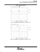
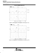
To determine the actual power dissipation of the regulator, use the following equation:
P
D
= (V
I
– V
O
) I
O
+ V
I
I
(GND)
(Watts)
Power dissipation resulting from quiescent current is negligible. When the power dissipation is excessive, the
thermal protection circuit is triggered.