
Datasheet
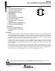

SN105125
150-mA LOW DROPOUT REGULATOR WITH POK
SLVS418 – JANUARY 2002
4
POST OFFICE BOX 655303 • DALLAS, TEXAS 75265
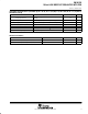
electrical characteristics, T
A
= 25°C, V
I
=5 V, V
(EN)
= V
I
, I
O
= 100 µA, C
L
= 1 µF(unless otherwise noted)
regulator V
O
PARAMETER TEST CONDITIONS MIN TYP MAX UNITS
Output voltage I
O
= 25 mA 1.2 V
V
O
Output voltage accuracy
I
O
= 0 –1% 1%
V
O
Output voltage accuracy
I
O
= 50 mA, T
A
= 0°C to 70°C (see Note 4) –2% 2%
I
Q
Quiescent supply current V
(EN)
≤ 0.8 V 1 µA
I
Ground terminal current (see Note 5)
I
O
= 0 150
A
I
(GND)
Ground terminal current (see Note 5)
I
O
= 150 mA
150
µA
I
L
Output load current 150 mA
I
(Limit)
Output current limit V
O
= 0 160 300 mA
∆V
(LNR)
Line regulation V
I
= 3 V to 5.25 V 10 mV
∆V
(LDR)
Load regulation I
O
= 0.1 mA to150 mA, See Note 6 2% 3%
V V
Dropout voltage
I
O
= 100 µA 1
V
V
I
– V
O
Dropout voltage
I
O
= 150 mA
1
V
C
L
Load capacitance ESR and capacitance tradeoffs 1 µF
I
(REV)
Reverse output current on V
I
V
I
= GND, V
O
= regulated voltage 50 µA
NOTES: 4. Assured by design, not tested in production.
5. Ground terminal current is the regulator quiescent current drawn from the supply to support the load current.
6. Regulation is measured at constant junction temperature using low duty cycle pulse testing. Devices are tested for load regulation
in the load range from 0.1 mA to 150 mA.
enable input
PARAMETER TEST CONDITIONS MIN TYP MAX UNITS
V
IL
Regulated shutdown V
I
= 3 V to 5.25 V regulated shutdown 0.8 V
V
IH
Regulated enabled V
I
= 3 V to 5.25 V regulated enabled 2 V
I
Enable input current
Shutdown, V
IL
≤ 0.8 V 0.01
A
I
(EN)
Enable input current
Enabled, V
IH
≥ 2 V
0.01
µA
Resistance discharge V
(EN)
≤ 0.8 V 500 Ω
thermal protection (see Note 4)
PARAMETER TEST CONDITIONS MIN TYP MAX UNITS
T
(SD)
Thermal shutdown 165 °C
T
(SDHYS)
Hysteresis 15 °C
NOTE 4: Assured by design, not tested in production.
power okay (see Note 7)
PARAMETER TEST CONDITIONS MIN TYP MAX UNITS
V
(POKLO)
Low threshold Output falls % of V
O
(power NOT okay) 85%
V
(POKTH)
High threshold Output reaches % of V
O
, starts delay timer (power okay) 90%
V
OL
V
O
out of regulation Fault condition, I
OL
= 100 µA 0.4 V
I
lkg
Leakage current V
I
= 5 V 1 µA
NOTE 7: Power okay is a function of the output voltage being 5% lower than the specified range. The function is a detection of one of the following:
over current, over temperature, or dropout.