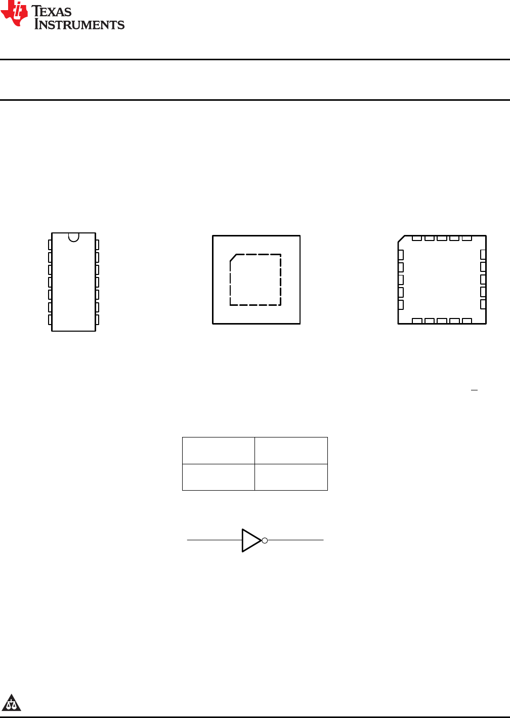
SN74AHC04 SN54AHC04 www.ti.com SCLS231N – OCTOBER 1995 – REVISED MAY 2013 HEX INVERTERS Check for Samples: SN74AHC04, SN54AHC04 FEATURES 1 Operating Range 2-V to 5.5-V Latch-Up Performance Exceeds 250 mA Per JESD 17 SN54AHC04 . . . JORWP ACKAGE SN74AHC04 . . . D,DB,DGV,N,NS, OR PW PACKAGE (TOP VIEW) 13 3 12 4 11 5 10 6 9 7 8 1Y 2A 2Y 3A 3Y 1 14 1Y 1A NC VCC 6A VCC VCC 6A 6Y 5A 5Y 4A 4Y SN54AHC04 . . .
SN74AHC04 SN54AHC04 SCLS231N – OCTOBER 1995 – REVISED MAY 2013 www.ti.com ABSOLUTE MAXIMUM RATINGS over operating free-air temperature range (unless otherwise noted) (1) VALUE UNIT Supply voltage range, VCC –0.5 to 7 V Input voltage range, VI (2) –0.5 to 7 V Output voltage range, VO (2) –0.5 to VCC + 0.
SN74AHC04 SN54AHC04 www.ti.com SCLS231N – OCTOBER 1995 – REVISED MAY 2013 ELECTRICAL CHARACTERISTICS over operating free-air temperature range (unless otherwise noted) PARAMETER TEST CONDITIONS SN74AHC04 MAX MIN MAX MIN Recommended MIN TYP 2V 1.9 2 1.9 1.9 1.9 MAX MIN 2.9 2.9 3 2.9 2.9 4.4 4.5 4.4 4.4 4.4 IOH = –4 mA 3V 2.58 2.48 2.48 2.48 IOH = –8 mA 4.5 V 3.94 VOL ICC VI = VCC or GND, Ci VI = VCC or GND IO = 0 V 3.8 0.1 0.1 0.1 0.1 3V 0.1 0.1 0.1 0.
SN74AHC04 SN54AHC04 SCLS231N – OCTOBER 1995 – REVISED MAY 2013 www.ti.com NOISE CHARACTERISTICS VCC = 5 V, CL = 50 pF, TA = 25°C (1) SN74AHC04 PARAMETER MIN TYP UNIT MAX VOL(P) Quiet output, maximum dynamic VOL 0.4 V VOL(V) Quiet output, minimum dynamic VOL –0.4 V VOH(V) Quiet output, minimum dynamic VOH 4.8 V VIH(D) High-level dynamic input voltage VIL(D) Low-level dynamic input voltage (1) 3.5 V 1.5 V Characteristics are for surface-mount packages only.
SN74AHC04 SN54AHC04 www.ti.
SN74AHC04 SN54AHC04 SCLS231N – OCTOBER 1995 – REVISED MAY 2013 www.ti.com REVISION HISTORY Changes from Revision M (July 2003) to Revision N Page • Changed document format from Quicksilver to DocZone. .................................................................................................... 1 • Extended operating temperature range to 125°C .................................................................................................................
PACKAGE OPTION ADDENDUM www.ti.
PACKAGE OPTION ADDENDUM www.ti.
PACKAGE OPTION ADDENDUM www.ti.com 25-Sep-2013 (1) The marketing status values are defined as follows: ACTIVE: Product device recommended for new designs. LIFEBUY: TI has announced that the device will be discontinued, and a lifetime-buy period is in effect. NRND: Not recommended for new designs. Device is in production to support existing customers, but TI does not recommend using this part in a new design. PREVIEW: Device has been announced but is not in production.
PACKAGE OPTION ADDENDUM www.ti.
PACKAGE MATERIALS INFORMATION www.ti.com 29-May-2013 TAPE AND REEL INFORMATION *All dimensions are nominal Device Package Package Pins Type Drawing SPQ Reel Reel A0 Diameter Width (mm) (mm) W1 (mm) B0 (mm) K0 (mm) P1 (mm) W Pin1 (mm) Quadrant SN74AHC04DBR SSOP DB 14 2000 330.0 16.4 8.2 6.6 2.5 12.0 16.0 Q1 SN74AHC04DGVR TVSOP DGV 14 2000 330.0 12.4 6.8 4.0 1.6 8.0 12.0 Q1 SN74AHC04DR SOIC D 14 2500 330.0 16.4 6.5 9.0 2.1 8.0 16.
PACKAGE MATERIALS INFORMATION www.ti.com 29-May-2013 *All dimensions are nominal Device Package Type Package Drawing Pins SPQ Length (mm) Width (mm) Height (mm) SN74AHC04DBR SSOP DB 14 2000 367.0 367.0 38.0 SN74AHC04DGVR TVSOP DGV 14 2000 367.0 367.0 35.0 SN74AHC04DR SOIC D 14 2500 367.0 367.0 38.0 SN74AHC04NSR SO NS 14 2000 367.0 367.0 38.0 SN74AHC04PWR TSSOP PW 14 2000 367.0 367.0 35.0 SN74AHC04RGYR VQFN RGY 14 3000 367.0 367.0 35.
MECHANICAL DATA MPDS006C – FEBRUARY 1996 – REVISED AUGUST 2000 DGV (R-PDSO-G**) PLASTIC SMALL-OUTLINE 24 PINS SHOWN 0,40 0,23 0,13 24 13 0,07 M 0,16 NOM 4,50 4,30 6,60 6,20 Gage Plane 0,25 0°– 8° 1 0,75 0,50 12 A Seating Plane 0,15 0,05 1,20 MAX PINS ** 0,08 14 16 20 24 38 48 56 A MAX 3,70 3,70 5,10 5,10 7,90 9,80 11,40 A MIN 3,50 3,50 4,90 4,90 7,70 9,60 11,20 DIM 4073251/E 08/00 NOTES: A. B. C. D. All linear dimensions are in millimeters.
MECHANICAL DATA MSSO002E – JANUARY 1995 – REVISED DECEMBER 2001 DB (R-PDSO-G**) PLASTIC SMALL-OUTLINE 28 PINS SHOWN 0,38 0,22 0,65 28 0,15 M 15 0,25 0,09 8,20 7,40 5,60 5,00 Gage Plane 1 14 0,25 A 0°–ā8° 0,95 0,55 Seating Plane 2,00 MAX 0,10 0,05 MIN PINS ** 14 16 20 24 28 30 38 A MAX 6,50 6,50 7,50 8,50 10,50 10,50 12,90 A MIN 5,90 5,90 6,90 7,90 9,90 9,90 12,30 DIM 4040065 /E 12/01 NOTES: A. B. C. D. All linear dimensions are in millimeters.
IMPORTANT NOTICE Texas Instruments Incorporated and its subsidiaries (TI) reserve the right to make corrections, enhancements, improvements and other changes to its semiconductor products and services per JESD46, latest issue, and to discontinue any product or service per JESD48, latest issue. Buyers should obtain the latest relevant information before placing orders and should verify that such information is current and complete.