
Datasheet


SCLS110E − DECEMBER 1982 − REVISED SEPTEMBER 2003
6
POST OFFICE BOX 655303 • DALLAS, TEXAS 75265
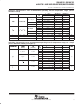
switching characteristics over recommended operating free-air temperature range, C
L
= 150 pF
(unless otherwise noted) (see Figure 1)
PARAMETER
FROM
TO
V
CC
T
A
= 25°C SN54HC151 SN74HC151
UNIT
PARAMETER
FROM
(INPUT)
TO
(OUTPUT)
V
CC
MIN TYP MAX MIN MAX MIN MAX
UNIT
2 V 107 350 525 440
A, B, or C Y or W
4.5 V 33 70 105 88
A, B, or C
Y or W
6 V 30 59 89 76
2 V 90 275 415 345
t
pd
Any D Y or W
4.5 V 29 51 83 69
ns
t
pd
Any D
Y or W
6 V 25 47 72 59
ns
2 V 67 205 310 255
G Y or W
4.5 V 21 41 62 51
G
Y or W
6 V 18 35 53 43
2 V 51 210 315 265
t
t
Y or W
4.5 V 16 42 63 53
ns
t
t
Y or W
6 V 14 36 53 45
ns
operating characteristics, T
A
= 25°C
PARAMETER TEST CONDITIONS TYP UNIT
C
pd
Power dissipation capacitance No load 70 pF
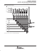
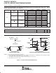
PARAMETER MEASUREMENT INFORMATION
VOLTAGE WAVEFORM
INPUT RISE AND FALL TIMES
50%50%
10%10%
90% 90%
V
CC
0 V
t
r
t
f
Input
VOLTAGE WAVEFORMS
PROPAGATION DELAY AND OUTPUT TRANSITION TIMES
50%
50%50%
10%10%
90% 90%
V
CC
V
OH
V
OL
0 V
t
r
t
f
Input
In-Phase
Output
50%
t
PLH
t
PHL
50% 50%
10% 10%
90%90%
V
OH
V
OL
t
r
t
f
t
PHL
t
PLH
Out-of-Phase
Output
Test
Point
From Output
Under Test
C
L
(see Note A)
LOAD CIRCUIT
NOTES: A. C
L
includes probe and test-fixture capacitance.
B. Phase relationships between waveforms were chosen arbitrarily. All input pulses are supplied by generators having the following
characteristics: PRR ≤ 1 MHz, Z
O
= 50 Ω, t
r
= 6 ns, t
f
= 6 ns.
C. The outputs are measured one at a time with one input transition per measurement.
D. t
PLH
and t
PHL
are the same as t
pd
.
Figure 1. Load Circuit and Voltage Waveforms