
Datasheet


Table Of Contents
- 1 Features
- 2 Applications
- 3 Description
- Table of Contents
- 4 Revision History
- 5 Pin Configuration and Functions
- 6 Specifications
- 7 Parameter Measurement Information
- 8 Detailed Description
- 9 Application and Implementation
- 10 Power Supply Recommendations
- 11 Layout
- 12 Device and Documentation Support
- 13 Mechanical, Packaging, and Orderable Information
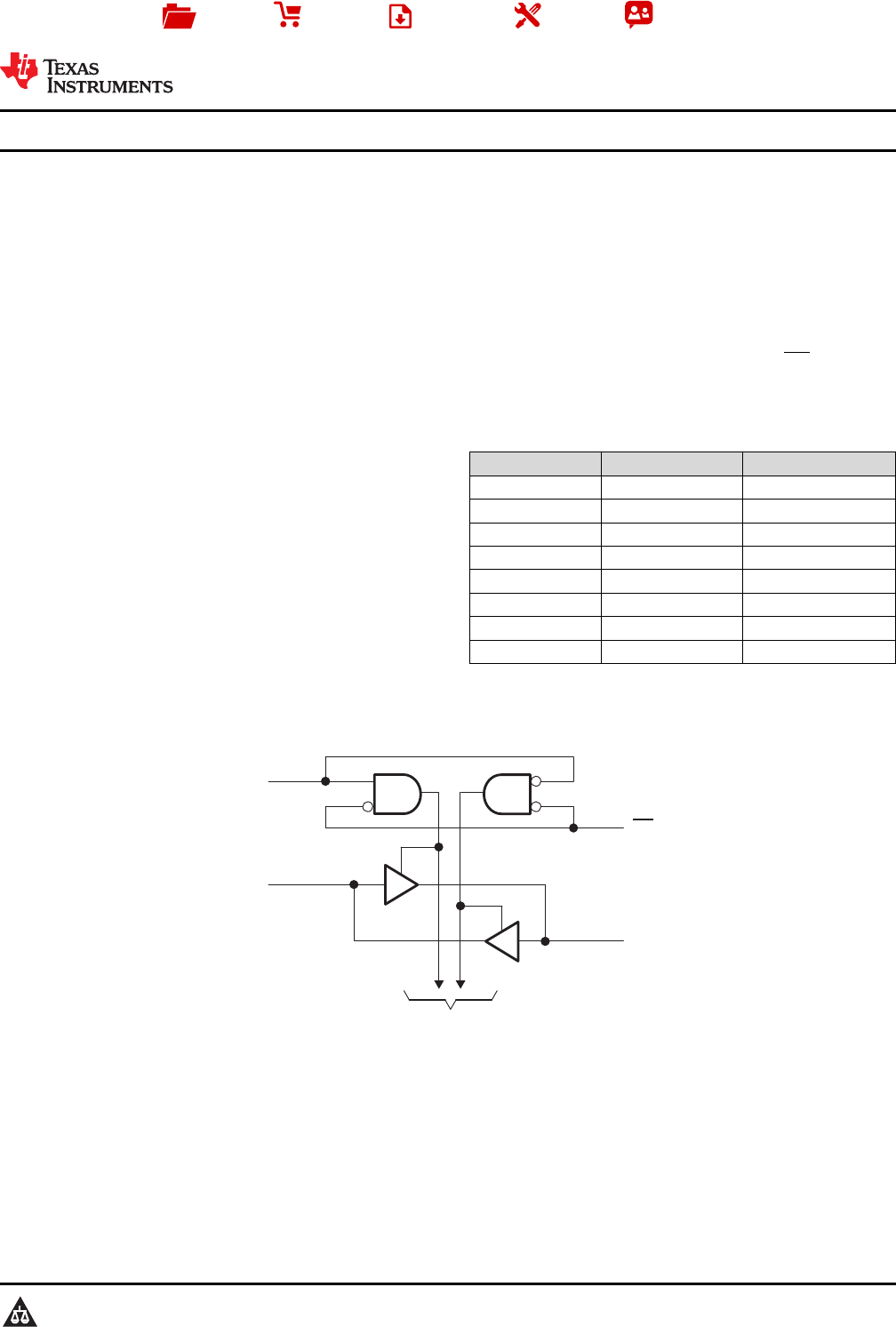
DIR
OE
A1
B1
1
2
18
19
To Seven Other Channels
Copyright © 2016, Texas Instruments Incorporated
Product
Folder
Sample &
Buy
Technical
Documents
Tools &
Software
Support &
Community
An IMPORTANT NOTICE at the end of this data sheet addresses availability, warranty, changes, use in safety-critical applications,
intellectual property matters and other important disclaimers. PRODUCTION DATA.
SN54HCT245
,
SN74HCT245
SCLS020F –MARCH 1984–REVISED AUGUST 2016
SNx4HCT245 Octal Bus Transceivers With 3-State Outputs
1
1 Features
1
• Operating Voltage Range of 4.5 V to 5.5 V
• High-Current 3-State Outputs Drive Bus Lines
Directly or up To 15-LSTTL Loads
• Low Power Consumption, 80-µA Maximum I
CC
• Typical t
pd
= 14 ns
• ±6-mA Output Drive at 5 V
• Low Input Current of 1 µA Maximum
• Inputs Are TTL-Voltage Compatible
2 Applications
• Factory Automation and Control
• Grid Infrastructure
• Electronic Point of Sale
• Multi-Function Printers
• Motor Drives
• Storage
• Telecom Infrastructure
3 Description
The SNx4HCT245 octal bus transceivers are
designed for asynchronous two-way communication
between data buses. The control-function
implementation minimizes external timing
requirements.
The SNx4HCT245 devices allow data transmission
from the A bus to the B bus or from the B bus to the
A bus, depending upon the logic level at the direction-
control (DIR) input. The output-enable (OE) input can
be used to disable the device so that the buses are
effectively isolated.
Device Information
(1)
PART NUMBER PACKAGE BODY SIZE (NOM)
SN54HCT245J CDIP (20) 24.20 mm × 6.92 mm
SN54HCT245FK LCCC (20) 8.89 mm × 8.89 mm
SN54HCT245W CFP (20) 13.09 mm × 6.92 mm
SN74HCT245DW SOIC (20) 12.80 mm × 7.50 mm
SN74HCT245N PDIP (20) 24.33 mm × 6.35 mm
SN74HCT245NS SOP (20) 12.60 mm × 5.30 mm
SN74HCT245PW TSSOP (20) 6.50 mm × 4.40 mm
SN74HCT245DB SSOP (20) 7.80 mm × 7.20 mm
(1) For all available packages, see the orderable addendum at
the end of the data sheet.
Logic Diagram (Positive Logic)