
Datasheet
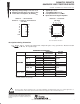


SN54HCT32, SN74HCT32
QUADRUPLE 2-INPUT POSITIVE-OR GATES
SCLS064E – NOVEMBER 1988 – REVISED AUGUST 2003
3
POST OFFICE BOX 655303 • DALLAS, TEXAS 75265
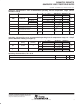
electrical characteristics over recommended operating free-air temperature range (unless
otherwise noted)
PARAMETER
TEST CONDITIONS
V
CC
T
A
= 25°C SN54HCT32 SN74HCT32
UNIT
PARAMETER
TEST CONDITIONS
V
CC
MIN TYP MAX MIN MAX MIN MAX
UNIT
V
OH
V
I
= V
IH
or V
IL
I
OH
= –20 µA
4.5 V
4.4 4.499 4.4 4.4
V
V
OH
V
I
= V
IH
or V
IL
I
OH
= –4 mA
4.5 V
3.98 4.3 3.7 3.84
V
V
OL
V
I
= V
IH
or V
IL
I
OL
= 20 µA
4.5 V
0.001 0.1 0.1 0.1
V
V
OL
V
I
= V
IH
or V
IL
I
OL
= 4 mA
4.5 V
0.17 0.26 0.4 0.33
V
I
I
V
I
= V
CC
or 0 5.5 V ±0.1 ±100 ±1000 ±1000 nA
I
CC
V
I
= V
CC
or 0, I
O
= 0 5.5 V 2 40 20 µA
∆I
CC
†
One input at 0.5 V or 2.4 V,
Other inputs at 0 or V
CC
5.5 V 1.4 2.4 3 2.9 mA
C
i
4.5 V
to 5.5 V
3 10 10 10 pF
†
This is the increase in supply current for each input that is at one of the specified TTL voltage levels, rather than 0 V or V
CC
.
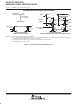
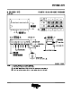
switching characteristics over recommended operating free-air temperature range, C
L
= 50 pF
(unless otherwise noted) (see Figure 1)
PARAMETER
FROM
TO
V
CC
T
A
= 25°C SN54HCT32 SN74HCT32
UNIT
PARAMETER
FROM
(INPUT)
TO
(OUTPUT)
V
CC
MIN TYP MAX MIN MAX MIN MAX
UNIT
t
pd
A or B
Y
4.5 V 15 24 35 30
ns
t
pd
A or B
Y
5.5 V 13 22 32 27
ns
t
t
Y
4.5 V 9 15 22 19
ns
t
t
Y
5.5 V 8 14 20 17
ns
operating characteristics, T
A
= 25°C
PARAMETER TEST CONDITIONS TYP UNIT
C
pd
Power dissipation capacitance per gate No load 20 pF
PRODUCT PREVIEW information concerns products in the formative or
design phase of development. Characteristic data and other
specifications are design goals. Texas Instruments reserves the right to
change or discontinue these products without notice.