
Datasheet
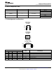


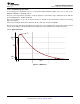


Time
I(A)
I
pk
90%
I
pk
10%
I
pk
t
r
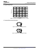
SN65220
,
SN65240
,
SN75240
www.ti.com
SLLS266H –FEBRUARY 1997–REVISED MAY 2015
11.2.2 Detailed Design Procedure
To effectively protect USB transceivers, use TVS diodes with breakdown voltages close to 6 V, such as the
SN65220, SN65240, or SN75220 devices.
Because of the TVS junction capacitance of 35 pF, apply these TVS diodes only to USB transceivers with full-
speed capability that is 12 Mbps maximum.
Place the TVS diodes as close to the board connector as possible to prevent transient energies from entering
further board space.
Connect the TVS diode between the data lines (D+, D–) and local circuit ground (GND).
Because noise transient represents high-speed frequencies, ensure low-inductance return paths for the transient
currents by providing a solid ground plane and using two VIAs connecting the TVS terminals to ground.
11.2.3 Application Curve
Figure 6. HBM Curve
Copyright © 1997–2015, Texas Instruments Incorporated Submit Documentation Feedback 9
Product Folder Links: SN65220 SN65240 SN75240