
Datasheet


SN75468
IN3
IN4
OUT1
OUT2
OUT3
OUT4
IN5
IN6
IN7
GND
OUT5
OUT6
OUT7
COM
IN1
IN2
3.3 V Logic
VSUP
3.3 V Logic
3.3 V Logic
VSUP
SN75468
,
SN75469
SLRS023E –DECEMBER 1976–REVISED JANUARY 2015
www.ti.com
10 Application and Implementation
NOTE
Information in the following applications sections is not part of the TI component
specification, and TI does not warrant its accuracy or completeness. TI’s customers are
responsible for determining suitability of components for their purposes. Customers should
validate and test their design implementation to confirm system functionality.
10.1 Application Information
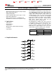
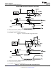
SN75468 will typically be used to drive a high voltage and/or current peripheral from an MCU or logic device that
cannot tolerate these conditions. The following design is a common application of SN75468, driving inductive
loads. This includes motors, solenoids & relays. Each load type can be modeled by what's seen in Figure 16.
10.2 Typical Application
Figure 16. SN75468 as Inductive Load Driver
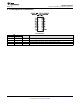
10.2.1 Design Requirements
For this design example, use the parameters listed in Table 1 as the input parameters.
Table 1. Design Parameters
DESIGN PARAMETER EXAMPLE VALUE
GPIO Voltage 3.3 V or 5.0 V
Coil Supply Voltage 12 V to 100 V
Number of Channels 7
Output Current (R
COIL
) 20 mA to 300 mA per channel
Duty Cycle 100%
10 Submit Documentation Feedback Copyright © 1976–2015, Texas Instruments Incorporated
Product Folder Links: SN75468 SN75469