
Datasheet


SN75476 THRU SN75478
DUAL PERIPHERAL DRIVERS
SLRS025A – DECEMBER 1976 – REVISED NOVEMBER 1995
Copyright 1995, Texas Instruments Incorporated
1
POST OFFICE BOX 655303 • DALLAS, TEXAS 75265
POST OFFICE BOX 1443
• HOUSTON, TEXAS 77251–1443
• Characterized for Use to 300 mA
• No Output Latch-Up at 55 V (After
Conducting 300 mA)
• High-Voltage Outputs (100 V Typ)
• Output Clamp Diodes for Transient
Suppression (300 mA, 70 V)
• TTL- or MOS-Compatible Diode-Clamped
Inputs
• pnp Transistor Inputs Reduce Input Current
• Standard Supply Voltage
• Suitable for Hammer-Driver Applications
• Plastic DIP (P) With Copper-Lead Frame
Provides Cooler Operation and Improved
Reliability
description
The SN75476 through SN75478 are dual
peripheral drivers designed for use in systems that
require high current, high voltage, and fast
switching times. The SN75476, SN75477, and
SN75478 provide AND, NAND, and OR drivers
respectively. These devices have diode-clamped
inputs as well as high-current, high-voltage clamp
diodes on the outputs for inductive transient
protection.
The SN75476, SN75477, and SN75478 drivers
are characterized for operation from 0°C to 70°C.
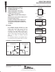
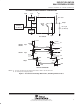
schematics of inputs and outputs
V
CC
Input
CLAMP
Output
GND
EQUIVALENT
OF EACH INPUT
TYPICAL
OF ALL OUTPUTS
1
2
3
4
8
7
6
5
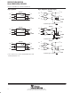
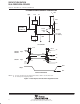
S
1A
1Y
GND
V
CC
2A
2Y
CLAMP
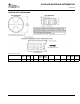
D OR P PACKAGE
(TOP VIEW)
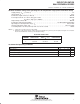
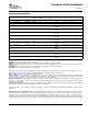
H = high level, L = low level
X = irrelevant
INPUTS
OUTPUT
Y
SN75476
(each AND driver)
AS
H
L
X
H
X
L
H
L
L
Function Tables
INPUTS
OUTPUT
Y
SN75477
(each NAND driver)
AS
H
L
X
H
X
L
L
H
H
INPUTS
OUTPUT
Y
SN75478
(each OR driver)
AS
H
X
L
X
H
L
H
H
L
PRODUCTION DATA information is current as of publication date.
Products conform to specifications per the terms of Texas Instruments
standard warranty. Production processing does not necessarily include
testing of all parameters.