
Marine Instruments User Manual

www.ti.com
4.6 DATA FLASH SUMMARY
bq27500
bq27501
System-Side Impedance Track™ Fuel Gauge
SLUS785 – SEPTEMBER 2007
Both the sets of keys for each level are 2 bytes each in length and are stored in data flash. The UNSEAL
key (stored at Unseal Key 0 and Unseal Key 1) and the FULL-ACCESS key (stored at Full Access Key
0 and Full Access Key 1) can only be updated when in FULL-ACCESS mode. The order of the bytes
entered through the Control( ) command is the reverse of what is read from the part. For example, if the
1st and 2nd word of Unseal Key 0 read returns 0x1234 and 0x5678, then the Control( ) should supply
0x3412 and 0x7856 to unseal the part.
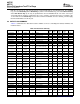
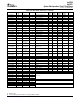
Table 4-7 summarizes the data flash locations available to the user, including their default, minimum, and
maximum values.
Table 4-7. Data Flash Summary
Subclass Data Min Max Default
Class Subclass Offset Name Units
ID Type Value Value Value
Configuration 2 Safety 0 OT Chg I2 0 1200 550 0.1 ° C
Configuration 2 Safety 2 OT Chg Time U1 0 60 2 s
Configuration 2 Safety 3 OT Chg Recovery I2 0 1200 500 0.1 ° C
Configuration 2 Safety 5 OT Dsg I2 0 1200 600 0.1 ° C
Configuration 2 Safety 7 OT Dsg Time U1 0 60 2 s
Configuration 2 Safety 8 OT Dsg Recovery I2 0 1200 550 0.1 ° C
Charge Inhibit
Configuration 32 0 Charge Inhibit Temp Low 12 –400 1200 0 0.1 ° C
Config
Charge Inhibit
Configuration 32 2 Charge Inhibit Temp High 12 –400 1200 450 0.1 ° C
Config
Charge Inhibit
Configuration 32 4 Temp Hys 12 0 100 50 0.1 ° C
Config
Configuration 34 Charge 2 Charging Voltage I2 0 20000 4200 mV
Configuration 34 Charge 4 Delta Temperature I2 0 500 50 0.1 ° C
Configuration 34 Charge 6 Suspend Temperature Low I2 –400 1200 –50 0.1 ° C
Configuration 34 Charge 8 Suspend Temperature High I2 –400 1200 550 0.1 ° C
Charge
Configuration 36 2 Taper Current I2 0 1000 100 mA
Termination
Charge
Configuration 36 4 Minimum Taper Charge I2 0 1000 64 mAh
Termination
Charge
Configuration 36 6 Taper Voltage I2 0 1000 100 mV
Termination
Charge
Configuration 36 8 Current Taper Window U1 0 60 40 s
Termination
Configuration 48 Data 0 SOC1 Set I2 0 700 100 mAh
Configuration 48 Data 6 Initial Standby Current I1 –256 0 –10 mA
Configuration 48 Data 7 Initial Max Load Current I2 –32767 0 –1000 mA
Configuration 48 Data 9 CC Threshold I2 100 32767 1400 mAh
Configuration 48 Data 12 Design Capacity I2 0 65535 1500 mAh
bq27500
Configuration 48 Data 39 Device Name S8 x x or –
bq27501
Configuration 49 Discharge 0 SOCF Set % I1 –1 100 6 %
Configuration 49 Discharge 2 SOCF Clear % I1 –1 100 8 %
Configuration 49 Discharge 4 Max Load RSOC I1 0 100 50 %
Manufacturer
System Data 58 0–31 Block A [0–31] H1 0x00 0xff 0x00 –
Info
Manufacturer
System Data 58 32–63 Block B [0–31] H1 0x00 0xff 0x00 –
Info
Manufacturer
System Data 58 64–95 Block C [0–31] H1 0x00 0xff 0x00 –
Info
GENERAL DESCRIPTION18 Submit Documentation Feedback