
Marine Instruments User Manual

www.ti.com
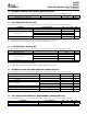
2 DEVICE INFORMATION
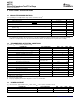
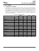
2.1 AVAILABLE OPTIONS
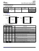
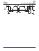
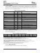
2.2 PIN DIAGRAMS
BAT
V
SS
SRN
SRP
V
CC
BAT_GD
SDA
SCL
1
2
3
4
5
6
12
11
10
9
8
7
BAT_LOW_
TS
1
2
3
4
5
6
12
11
10
9
8
7
BI/TOUT
BAT
V
SS
V
CC
BAT_LOW_
TS
BI/TOUT
NC
SRN
SRP
BAT_GD
SDA
SCL
RID
bq27500
bq27501
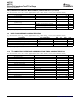
2.3 TERMINAL FUNCTIONS
bq27500
bq27501
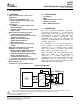
System-Side Impedance Track™ Fuel Gauge
SLUS785 – SEPTEMBER 2007
COMMUNICATION TAPE and REEL
PART NUMBER PACKAGE
(1)
T
A
FORMAT QUANTITY
bq27500DRZR 3000
bq27500DRZT 300
12-pin, 2,5 mm x 4,0 mm
–40 ° C to 85 ° C I
2
C
SON
bq27501DRZR
(2)
3000
bq27501DRZT
(2)
300
(1) For the most current package and ordering information, see the Package Option Addendum at the end of this document, or see the TI
website at www.ti.com .
(2) Product Preview
TERMINAL
I/O
(1)
DESCRIPTION
NAME NAME
PIN NO.
bq27500 bq27501
Battery Low output indicator. Active high by default, though polarity can be configured
1 BAT_LOW BAT_LOW O
through the [BATL_POL] in Operation Configuration Push-pull output.
Battery-insertion detection input. Power pin for pack thermistor network. Thermistor
2 BI/TOUT BI/TOUT I/O
multiplexer control pin. Open-drain I/O. use with pull-up resistor > 1M Ω (1.8M Ω typical)
3 TS TS P Pack thermistor voltage sense (use 103AT-type thermistor). ADC input.
4 BAT BAT I Cell-voltage measurement input. ADC input.
5 V
CC
V
CC
P Processor power input. Decouple with 0.1 μ F capacitor, minimum.
6 V
SS
V
SS
P Device ground.
Analog input pin connected to the internal coulomb-counter where SRP is nearest the
7 SRP SRP IA
CELL- connection. Connect to 5-20m Ω sense resistor.
Analog input pin connected to the internal coulomb-counter where SRN is nearest the
8 SRN SRN IA
PACK- connection. Connect to 5-20m Ω sense resistor.
No connection (bq27500). Resistor ID input (bq27501). Analog input with current sourcing
9 NC RID –, I
capabilities.
Slave I
2
C serial communications data line for communication with system ( Master).
10 SDA SDA I/O
Open-drain I/O. Use with 10k Ω pull-up resistor (typical).
Slave I
2
C serial communications clock input line for communication with system ( Master).
11 SCL SCL I
Open-drain I/O. Use with 10k Ω pull-up resistor (typical).
Battery Good indicator. Active low by default, though polarity can be configured through
12 BAT_GD BAT_GD O
the [BATG_POL] of Operation Configuration. Open-drain output.
(1) I/O = Digital Input/Output, IA = Analog Input, P = Power Connection
Submit Documentation Feedback DEVICE INFORMATION 3