
Marine Instruments User Manual

www.ti.com
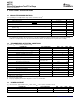
3 ELECTRICAL SPECIFICATIONS
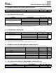
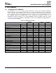
3.1 ABSOLUTE MAXIMUM RATINGS
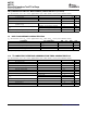
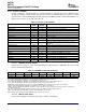
3.2 RECOMMENDED OPERATING CONDITIONS
3.3 POWER-ON RESET
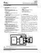
bq27500
bq27501
System-Side Impedance Track™ Fuel Gauge
SLUS785 – SEPTEMBER 2007
over operating free-air temperature range (unless otherwise noted)
(1)
PARAMETER VALUE UNIT
V
CC
Supply voltage range –0.3 to 2.75 V
V
IOD
Open-drain I/O pins (BI_TOUT, SDA, SDL, BAT_GD) –0.3 to 6 V
V
BAT
BAT input pin –0.3 to +6
V
I
Input voltage range to all other pins (TS, SRP, SRN, RID [bq27501 only], NC –0.3 to V
CC
+ 0.3 V
[bq27500 only])
1 kV
ESD Human Body Model (HMB)
2 kV
T
F
Functional temperature range –40 to 100 ° C
T
STG
Storage temperature range –65 to 150 ° C
(1) Stresses beyond those listed under absolute maximum ratings may cause permanent damage to the device. These are stress ratings
only, and functional operation of the device at these or any other conditions beyond those indicated under recommended operating
conditions is not implied. Exposure to absolute-maximum-rated conditions for extended periods may affect device reliability.
T
A
= 25 ° C, V
CC
= 2.5 V (unless otherwise noted)
PARAMETER TEST CONDITIONS MIN TYP MAX UNIT
V
CC
Supply Voltage 2.4 2.5 2.6 V
I
CC
Normal operating mode current
(1)
95 μ A
I
SLP
Low-power storage mode current
(2)
15 μ A
I
CC
Hibernate operating mode current
(3)
2 μ A
V
OL
Output voltage low (SDA, BAT_LOW, BI/TOUT) I
OL
= 0.5 mA 0.4 V
V
OH(PP)
Output high voltage (BAT_LOW) I
OH
= –1 mA V
CC
–0.5 V
External pull-up resistor
V
OH(OD)
Output high voltage (SDA, SCL, BI/TOUT) V
CC
–0.5 V
connected to V
CC
V
IL
Input voltage low (SDA, SCL) –0.3 0.8
V
V
IH(OD)
Input voltage high (SDA, SCL, BI/TOUT) 2 6
C
IN
Input capacitance 5 pF
V
A1
Input voltage range (TS, RID [bq27501 only]) V
SS
–0.125 2 V
V
A2
Input voltage range (BAT) V
SS
–0.125 5 V
V
A3
Input voltage range (SRP, SRN) V
SS
–0.125 0.125 V
t
PUCD
Power up communication delay 250 ms
T
A
Operating free-air temperature range –40 85 ° C
(1) High level of system activity.
(2) Low level of system activity.
(3) Fuel gauge algorithm power inactive. Only able to receive I
2
C communication.
T
A
= –40 ° C to 85 ° C, Typical Values at T
A
= 25 ° C and V
BAT
= 3.6 V (unless otherwise noted)
PARAMETER TEST CONDITIONS MIN TYP MAX UNIT
V
IT+
Positive-going battery voltage input at V
CC
2.09 2.20 2.31 V
V
HYS
45 115 185 mV
ELECTRICAL SPECIFICATIONS4 Submit Documentation Feedback