
Marine Instruments User Manual

www.ti.com
3.9 DATA FLASH MEMORY CHARACTERISTICS
3.10 I
2
C-COMPATIBLE INTERFACE COMMUNICATION TIMING CHARACTERISTICS
bq27500
bq27501
System-Side Impedance Track™ Fuel Gauge
SLUS785 – SEPTEMBER 2007
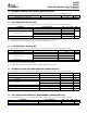
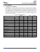
ADC (TEMPERATURE AND CELL MEASUREMENT) CHARACTERISTICS (continued)
T
A
= –40 ° C to 85 ° C, 2.4 V < V
CC
< 2.6 V; Typical Values at T
A
= 25 ° C and V
CC
= 2.5 V (unless otherwise noted)
PARAMETER TEST CONDITIONS MIN TYP MAX UNIT
t
ADC_CONV
Conversion time 125 ms
Resolution 14 15 bits
V
ADC_OS
Input offset 1 mV
Z
ADC1
Effective input resistance (TS, RID 8 M Ω
[bq27501 only])
bq27500/1 not measuring cell voltage 8 M Ω
Z
ADC2
Effective input resistance (BAT)
(1)
bq27500/1 measuging cell voltage 100 k Ω
I
ADC_LKG
Input Leakage Current
(1)
0.3 μ A
(1) Specified by design. Not tested in production.
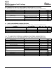
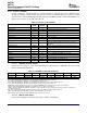
T
A
= –40 ° C to 85 ° C, 2.4 V < V
CC
< 2.6 V; Typical Values at T
A
= 25 ° C and V
CC
= 2.5 V (unless otherwise noted)
PARAMETER TEST CONDITIONS MIN TYP MAX UNIT
t
ON
Data retention See
(1)
10
(1)
Years
Flash programming write-cycles See
(1)
20,000 Cycles
t
WORDPROG
Word programming time See
(1)
2 ms
I
CCPROG
Flash-write supply current 5 10 mA
(1) Specified by design. Not production tested
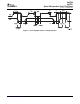
T
A
= –40 ° C to 85 ° C, 2.4 V < V
CC
< 2.6 V; Typical Values at T
A
= 25 ° C and V
CC
= 2.5 V (unless otherwise noted)
PARAMETER TEST CONDITIONS MIN TYP MAX UNIT
t
r
SCL/SDA rise time 1 μ s
t
f
SCL/SDA fall time 300 ns
t
w(H)
SCL pulse width (high) 4 μ s
t
w(L)
SCL pulse width (low) 4.7 μ s
t
su(STA)
Setup for repeated start 4.7 μ s
t
d(STA)
Start to first falling edge of SCL 4 μ s
t
su(DAT)
Data setup time 250 ns
Receive mode 0
t
h(DAT)
Data hold time ns
Transmit mode 300
t
su(STOP)
Setup time for stop 4 μ s
t
BUF
Bus free time between stop and start 4.7 μ s
f
SCL
Clock frequency 10 100 kHz
t
BUSERR
Bus error timeout 17.3 21.2 s
ELECTRICAL SPECIFICATIONS6 Submit Documentation Feedback