TAS5102EVM and TAS5103EVM for the TAS5102 and TAS5103 Digital Amplifier Power Output Stages User's Guide Literature Number: SLLU106 August 2008
SLLU106 – August 2008 Submit Documentation Feedback
Contents 1 Related Documentation from Texas Instruments...................................................................... 5 1.1 2 3 4 5 Additional Documentation ................................................................................................ 5 Overview ............................................................................................................................. 5 2.1 TAS5102EVM and TAS5103EVM Features ................................................................
www.ti.com List of Figures 1 2 3 4 Physical Structure for TAS5102/3EVM ................................................................................... 6 Modulator and Power Stage Board Connection Example .............................................................. 7 TAS5086 GUI Window ...................................................................................................... 8 Recommended Power-Up Sequence ...................................................................................
User's Guide SLLU106 – August 2008 TAS5102EVM and TAS5103EVM for the TAS5102 and TAS5103 Digital Amplifier Power Output Stages This user's guide describes the operation of the TAS5102 and TAS5103 evaluation modules (EVM) from Texas Instruments.
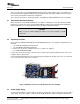
Overview www.ti.com The TAS5103 is a compact, high-power, digital amplifier power stage designed to drive an 8-Ω loudspeaker up to 15 W/channel at 10% THD+N. It contains integrated gate-drive, four matched and electrically isolated enhancement-mode N-channel power DMOS transistors, and protection/fault-reporting circuitry. The DAP package has a PowerPAD™ package on the bottom side for heat transfer through the printed-circuit board.
Quick-Setup Guide www.ti.com 3 Quick-Setup Guide This section describes the TAS5102/3EVM board in regards to power supplies and system interfaces. It provides information regarding handling and unpacking, absolute operating conditions, and a description of the factory default switch and jumper configuration. The section also provides a step-by-step guide to configuring the TAS5102/3EVM for device evaluation. 3.
Quick-Setup Guide www.ti.com Table 2. Recommended Supply Voltage Description Voltage Limitations Current Requirement Connector Output stage power supply 8 V – 23 V 5A Red/black CAUTION Applying voltages above the limitations given in Table 2 can cause permanent damage to your hardware. 3.4 GUI Software Installation The TAS5086 GUI provides easy control of all registers in TAS5086. To install the GUI, run the setup file from the TAS5102/3 CD-ROM.
System Interfaces www.ti.com 3.5 Operational Sequence and Indicators • • • • • • 4 After connecting the power supply and turning it on, the power supply current must be ~50 mA. The amplifier reset LED must be on. – The PVDD and 3.3-V LEDs must be on. If not, check the connections to the power supply. Connect the SPDIF cable, either optical or coaxial, to an SPDIF source. Connect the USB cable and the USB LED (blue LED must be on).
System Interfaces www.ti.com The recommended TAS5102/3 power-up sequence is shown in Figure 4. For proper TAS5102/3 operation, the RESET signal should be kept low during power up. RESET is pulled low during power up for 200 ms by the onboard reset generator (U2). System power supply Output stage power supply RESET >1 ms Figure 4. Recommended Power-Up Sequence 4.2 J1 Amplifier Connection to MC012 Controller Module Table 4.
Protection www.ti.com 4.4 SPDIF Optical Input Connector This connector is a standard TOSLINK connector that connects the SPDIF digital audio input to the SPDIF receiver on the HPL-MC012 PCB. This connector, or the SPDIF co-axial input, is used, but not both connectors at the same time. 4.5 SPDIF Co-Axial Input Connector This connector is a standard RCA connector that connects the SPDIF digital audio input to the SPDIF receiver on the HPL-MC012 PCB.
FROM MATING CONNECTOR 0 1 2 3 4 5 6 7 0 0 0 0 1 1 1 1 MODE DIF2 DIF0 0 1 0 1 0 1 0 1 0 0 1 1 0 0 1 1 16 Bit / RJ 18 Bit / RJ 20 Bit / RJ 24 Bit / RJ 24 Bit / LJ 24 Bit / I2S 24 Bit / LJ 24 Bit / I2S SDTO/DATA BICK/BCK I/O LRCK 64fs O 64fs O 64fs O 64fs O 64fs O 64fs O 64-128fs I 64-128fs I 3.
SLLU106 – August 2008 Submit Documentation Feedback I2S IN USB IN MASTER RESET CONTROL AMP USB INPUT / RESET / PWM MODULATOR USB LINK MUTE TO SPDIF TI TAS5086DBT U4 Filename: HPL-MC012.sch of 4 Tue Dec 19, 2006 Drawn By:LDN Sheet 2 PROJECT: CONTROLLER FOR TAS5132DDV2EVM Mod: NC PCB Rev: NC Schematic Rev: NC Print Date Save Date: DECEMBER 7 2006 Design Team: FRED SHIPLEY CX OVER TEMP WARNING SHUT DOWN TO TAS5132DDV2EVM www.ti.
HPL-MC012 Composite Drawings A.2 HPL-MC012 Composite Drawings 14 Design Documents www.ti.
SLLU106 – August 2008 Submit Documentation Feedback 1 1 RESERVED RESERVED Same As BTL Mode + In SE Mode OUT_x Is Hi-Z BTL Mode* BTL Mode Protection Scheme IN 2-3 IN (TAS5012) (BD MODE) Range = 8-23V EMI SNUBBER *BOARD SHIPPED IN 2N-BTL MODE RESERVED JP1 JP2 JP3 HPL-MC013 Output Configuration MODE TABLE 2N AD/BD Modulation 2 Channel BTL 1N AD Modulation 2 Channel BTL 1N AD Modulation 4 Channel SE PWM Input POWER SUPPLY INPUTS 0 1 0 0 0 1 M2 M1 OUT 1-2 OUT (TAS5086) (AD MODE) HPL-MC01
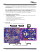
TAS5102/3EVM Composite Drawings A.4 TAS5102/3EVM Composite Drawings 16 Design Documents www.ti.
SLLU106 – August 2008 Submit Documentation Feedback Range = 8-23V POWER SUPPLY INPUTS CONTROLLER EMI SNUBBER RESERVED Same As BTL Mode + In SE Mode OUT_x Is Hi-Z BTL Mode* BTL Mode Protection Scheme OUT 1-2 OUT IN 2-3 IN (TAS5012) (BD MODE) HPL-MC013 JP1 JP2 JP3 (TAS5086) (AD MODE) HPL-MC012 PWM MODE JUMPERS RESERVED RESERVED 1 Output Configuration 1 PWM Input 2N AD/BD Modulation 2 Channel BTL 1N AD Modulation 2 Channel BTL 1N AD Modulation 4 Channel SE 0 1 0 0 0 1 M2 M1 MODE TABLE
TAS5102/3EVM Composite Drawings 18 Design Documents www.ti.
Heat Sink Drawing www.ti.com A.5 Heat Sink Drawing A.6 Parts List Table A-1.
Parts List www.ti.com Table A-1.
Parts List www.ti.com Table A-1. Bill of Materials for HPL-MC012 (continued) Description RefDes RES 0.05 OHM 1/4W 1% SMD 0805 R38 QTY 1 MFG Vishay/Dale WSL0805R0500FEA18 MFG Part# RES 2.7 OHM 1/10W 5% SMD 0805 R55, R61 2 Panasonic ERJ-6RQJ2R7V RES 3.3 OHM 1/10W 5% SMD 0805 R39, R42, R70 3 Panasonic ERJ-6RQJ3R3V RES 49.9 OHM 1/10W 1% SMD 0805 R41 1 Panasonic ERJ-6ENF49R9V RES 1.00K OHM 1/10W 1% SMD 0805 R40 1 Panasonic ERJ-6ENF1001V RES 37.
Parts List www.ti.com Table A-2. Bill of Materials for TAS5103EVM (continued) Description RefDes CAP 47UFD 16V RAD ALUM ELEC FC C38 QTY 1 MFG Panasonic EEU-FC1C470 MFG Part# CAP 220UFD 35V ALUM ELEC M-SERIES ROHS C2, C18, C22 3 Panasonic ECA-1VM221BJ CAP 330UFD 35V ALUM ELEC M-SERIES ROHS C6 1 Panasonic ECA-1VM331B RES 3.3 OHM 1/16W 5% SMD 0603 R4, R5, R6, R7 4 Yageo 9C06031A3R30JLHFT RES 357 OHM 1/16W 1% SMD 0603 R10 1 Panasonic ERJ-3EKF3570V RES 1.
Parts List www.ti.com Table A-3. Bill of Materials for TAS5102EVM (continued) Description RefDes RES 3.3 OHM 1/16W 5% SMD 0603 R4, R5, R6, R7 4 Yageo 9C06031A3R30JLHFT RES 357 OHM 1/16W 1% SMD 0603 R10 1 Panasonic ERJ-3EKF3570V RES 1.8K OHM 1/16W 5% SMD 0603 R8 1 Yageo 9C06031A1801JLHFT RES 22.1K OHM 1/16W 1% SMD 0603 R3 1 Panasonic ERJ-3EKF2212V RES 1.
EVALUATION BOARD/KIT IMPORTANT NOTICE Texas Instruments (TI) provides the enclosed product(s) under the following conditions: This evaluation board/kit is intended for use for ENGINEERING DEVELOPMENT, DEMONSTRATION, OR EVALUATION PURPOSES ONLY and is not considered by TI to be a finished end-product fit for general consumer use. Persons handling the product(s) must have electronics training and observe good engineering practice standards.
IMPORTANT NOTICE Texas Instruments Incorporated and its subsidiaries (TI) reserve the right to make corrections, modifications, enhancements, improvements, and other changes to its products and services at any time and to discontinue any product or service without notice. Customers should obtain the latest relevant information before placing orders and should verify that such information is current and complete.