
Digital Amplifier User's Guide


3.4 GUI Software Installation
Quick-Setup Guide
www.ti.com
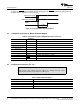
Table 2. Recommended Supply Voltage
Description Voltage Limitations Current Requirement Connector
Output stage power supply 8 V – 23 V 5 A Red/black
CAUTION
Applying voltages above the limitations given in Table 2 can cause permanent
damage to your hardware.
The TAS5086 GUI provides easy control of all registers in TAS5086. To install the GUI, run the setup file
from the TAS5102/3 CD-ROM.
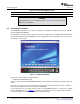
After installation, turn on the power supply, and connect the USB cable to the Modulator/Controller board.
Start the GUI program from The Windows™ menu. (Program Files/Texas Instruments Inc) The start-up of
the GUI takes few seconds.
Figure 3. TAS5086 GUI Window
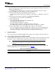
From the files menu, load the configuration file:
TAS5102 EVM Configuration.cfg
The file is located on the TAS5102/3EVM CD-ROM. This file contains all settings for a default setup of the
EVM.
For easy access of the file, it is recommended to copy the files into directory where the GUI is installed.
Default is C:\Program Files\Texas Instruments Inc\TAS5086\.
For more advanced use of the GUI and the features of the TAS5086 modulator, see the GUI User’s Guide
and the TAS5086 data sheet (SLES131 ). The GUI User's Guide can be accessed by clicking on Help in
the toolbar and then selecting User's Guide in the drop-down menu.
TAS5102EVM and TAS5103EVM for the TAS5102 and TAS5103 Digital Amplifier Power Output Stages8 SLLU106 – August 2008
Submit Documentation Feedback