
Digital Amplifier User's Guide


Contents
1 Related Documentation from Texas Instruments ...................................................................... 5
1.1 Additional Documentation ................................................................................................ 5
2 Overview ............................................................................................................................. 5
2.1 TAS5102EVM and TAS5103EVM Features ........................................................................... 6
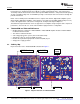
2.2 PCB Key Map.............................................................................................................. 6
3 Quick-Setup Guide ............................................................................................................... 7
3.1 Electrostatic Discharge Warning ........................................................................................ 7
3.2 Unpacking the EVM ....................................................................................................... 7
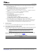
3.3 Power Supply Setup ...................................................................................................... 7
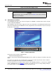
3.4 GUI Software Installation ................................................................................................. 8
3.5 Operational Sequence and Indicators .................................................................................. 9
4 System Interfaces ................................................................................................................ 9
4.1 Power Supply (PSU) Interface (PVDD and GND) .................................................................... 9
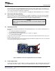
4.2 J1 Amplifier Connection to MC012 Controller Module .............................................................. 10
4.3 Loudspeaker Connectors (J3 - J6) .................................................................................... 10
4.4 SPDIF Optical Input Connector ........................................................................................ 11
4.5 SPDIF Co-Axial Input Connector ...................................................................................... 11
4.6 USB Connector .......................................................................................................... 11
5 Protection .......................................................................................................................... 11
5.1 Short-Circuit Protection and Fault-Reporting Circuitry .............................................................. 11
5.2 Fault Reporting ........................................................................................................... 11
Appendix A Design Documents ................................................................................................... 12
A.1 HPL-MC012 Schematic ................................................................................................. 12
A.2 HPL-MC012 Composite Drawings .................................................................................... 14
A.3 TAS5102/3EVM Schematic ............................................................................................ 15
A.4 TAS5102/3EVM Composite Drawings ................................................................................ 16
A.5 Heat Sink Drawing ....................................................................................................... 19
A.6 Parts List .................................................................................................................. 19
Important Notices ............................................................................................................... 24
SLLU106 – August 2008 Table of Contents 3
Submit Documentation Feedback