
Digital Amplifier User's Guide


www.ti.com
List of Figures
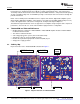
1 Physical Structure for TAS5102/3EVM ................................................................................... 6
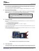
2 Modulator and Power Stage Board Connection Example .............................................................. 7
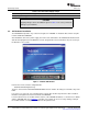
3 TAS5086 GUI Window ...................................................................................................... 8
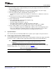
4 Recommended Power-Up Sequence .................................................................................... 10
List of Tables
1 Related Documentation From Texas Instruments ....................................................................... 5
2 Recommended Supply Voltage ............................................................................................ 8
3 Recommended Supply Voltages ........................................................................................... 9
4 J9/J10 Pin Description Amplifier/Controller Connector ................................................................ 10
5 Output Pin Description ..................................................................................................... 10
6 TAS5102 Warning/Error Signal Decoding .............................................................................. 11
A-1 Bill of Materials for HPL-MC012 .......................................................................................... 19
A-2 Bill of Materials for TAS5103EVM ....................................................................................... 21
A-3 Bill of Materials for TAS5102EVM ....................................................................................... 22
4 List of Figures SLLU106 – August 2008
Submit Documentation Feedback