TAS5508−5121K8EVM Evaluation Module for the TAS5508B 8-Channel Digital Audio PWM Processor and the TAS5121 Digital Amplifier Power Output Stage User’s Guide
IMPORTANT NOTICE Texas Instruments Incorporated and its subsidiaries (TI) reserve the right to make corrections, modifications, enhancements, improvements, and other changes to its products and services at any time and to discontinue any product or service without notice. Customers should obtain the latest relevant information before placing orders and should verify that such information is current and complete.
EVALUATION BOARD/KIT IMPORTANT NOTICE Texas Instruments (TI) provides the enclosed product(s) under the following conditions:. This evaluation board/kit is intended for use for ENGINEERING DEVELOPMENT, DEMONSTRATION, OR EVALUATION PURPOSES ONLY and is not considered by TI to be a finished end−product fit for general consumer use. Persons handling the product(s) must have electronics training and observe good engineering practice standards.
EVM WARNINGS AND RESTRICTIONS It is important to operate this EVM within the input voltage range of 0–29.5 V and the output voltage range of 15–20 V for the system supply. Exceeding the specified input range may cause unexpected operation and/or irreversible damage to the EVM. If there are questions concerning the input range, please contact a TI field representative prior to connecting the input power.
Preface Read This First About This Manual This manual describes the operation of the TAS5508−5121K8EVM evaluation module from Texas Instruments. How to Use This Manual This document contains the following chapters: - Chapter 1 — Overview - Chapter 2 — System Interfaces - Chapter 3 — Protection Information About Cautions and Warnings This manual may contain cautions and warnings. This is an example of a caution statement.
Related Documentation From Texas Instruments The following table contains a list of data manuals that have detailed descriptions of the integrated circuits used in the design of the TAS5508−5121K8EVM. The data manuals can be obtained at the URL http://www.ti.com.
Contents 1 Overview . . . . . . . . . . . . . . . . . . . . . . . . . . . . . . . . . . . . . . . . . . . . . . . . . . . . . . . . . . . . . . . . . . . . . . . . 1-1 1.1 TAS5508−5121K8EVM Features . . . . . . . . . . . . . . . . . . . . . . . . . . . . . . . . . . . . . . . . . . . . . 1-2 1.2 PCB Key Map . . . . . . . . . . . . . . . . . . . . . . . . . . . . . . . . . . . . . . . . . . . . . . . . . . . . . . . . . . . . . . 1-3 2 System Interfaces . . . . . . . . . . . . . . . . . . . . . . . . . .
Figures 1−1 1−2 2−1 2−2 2−3 2−4 2−5 2−6 2−7 2−8 2−9 Integrated PurePath Digitalt Amplifier System . . . . . . . . . . . . . . . . . . . . . . . . . . . . . . . . . . . Physical Structure for the TAS5508−5121K8EVM (Rough Outline) . . . . . . . . . . . . . . . . . . . Recommended Power-Up Sequence . . . . . . . . . . . . . . . . . . . . . . . . . . . . . . . . . . . . . . . . . . . . J71 and J70 Pin Numbers . . . . . . . . . . . . . . . . . . . . . . . . . . . . . . . . . . . . . . . . . . . . . . . . . . .
Chapter 1 Overview The TAS5508−5121K8EVM PurePath Digital™ customer evaluation amplifier module demonstrates two audio integrated circuits, TAS5508B and TAS5121, from Texas Instruments (TI). The TAS5508BPAG is a high-performance 32-bit (24-bit input) multichannel PurePath Digital pulse width modulator (PWM) based on Equibit™ technology, with a new fully symmetrical AD modulation scheme. It accepts an input sample rate from 32 kHz to 192 kHz.
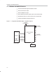
TAS5508−5121K8EVM Features 1.1 TAS5508−5121K8EVM Features - 8-channel PurePath Digital evaluation module - Stereo channel line output - Stereo headphone output - Self-contained protection system (short circuit and thermal) - Standard I2S and I2C control connector for TI input board - Double-sided plated-through PCB layout Figure 1−1.
PCB Key Map 1.2 PCB Key Map The physical structure for the TAS5508−5121K8EVM is illustrated in Figure 1−2. Figure 1−2.
1-4
Chapter 2 This chapter describes the TAS5508−5121K8EVM board in regards to power supplies and system interfaces. Topic Page 2.1 Power Supply (PSU) Interface (J70, J71, and J73) . . . . . . . . . . . . . . . . 2-2 2.2 Loudspeaker Connectors (J100 . . . J800) . . . . . . . . . . . . . . . . . . . . . . . 2-4 2.3 Line Out Connectors (J950 and J951) . . . . . . . . . . . . . . . . . . . . . . . . . . . 2-4 2.4 Headphone Connector (J900) . . . . . . . . . . . . . . . . . . . . . . . .
Power Supply (PSU) Interface (J70, J71, and J73) 2.1 Power Supply (PSU) Interface (J70, J71, and J73) The TAS5508−5121K8EVM module must be powered from external power supplies. High-end audio performance requires a stabilized power supply with low ripple voltage and low output impedance. Note: The length of the power supply cable must be minimized. Increasing length of PSU cable is equal to increasing the distortion for the amplifier at high output levels and low frequencies.
Power Supply (PSU) Interface (J70, J71, and J73) Table 2−2. J71 Pin Description Pin No. Net-Name at Schematics Description 1 V-HBRIDGE Output-stage power supply 2 − System power supply 3 GND Ground 4 GND Ground Table 2−3. J70 Pin Description (Optional − Use to decrease of impedance to reach better performance) Pin No.
Loudspeaker Connectors (J100 . . . J800) Table 2−5. J72 Pin Description Pin No. Net-Name at Schematics Description 1 — Reserved for future use 2 V-HBRIDGE Sense of output power supply 3 GND Ground 4 RESET System reset (bidirectional) 5 PSVC Power-supply volume control signal 2.2 Loudspeaker Connectors (J100 . . . J800) Both positive and negative speaker outputs are floating and may not be connected to ground (e.g., through an oscilloscope). Figure 2−5. J100 . . .
Headphone Connector (J900) 2.4 Headphone Connector (J900) Figure 2−7. J900 Pin Numbers 1 2 3 4 (PCB connector top view) Table 2−8. J900 Pin Description Pin No. Net-Name at Schematics Description 1 OUT−L Left headphone output 2 GND Ground 3 — For future use 4 OUT−R Right headphone output 2.5 Line Output Select (J50) Figure 2−8. J50 Pin Numbers Table 2−9. J50 Pin Description Pin No. Description 1−2 Line outputs enabled 2−3 Line outputs disabled 2.6 Headphone Select (J32) Figure 2−9.
Control Interface (J30) 2.7 Control Interface (J30) This interface connects the TAS5508−5121K8EVM board to a TI input board. Table 2−11. J30 Pin Description Pin No. Net-Name at Schematics Description 1 GND Ground 2 PSVC−MCPU Power supply volume control from (mC) input board 3 GND Ground 4 RESET System reset (bidirectional). Activate MUTE before RESET for quiet reset.
Digital Audio Interface (J40) 2.8 Digital Audio Interface (J40) The digital audio interface contains digital audio signal data (I2S), clocks, etc. See the TAS5508B Data Manual (SLES162) for signal timing and details not explained in this document. Table 2−12.J40 Pin Description Pin No. Net-Name at Schematics Description 1 GND Ground 2 MCLK Master clock input. Low-jitter system clock for PWM generation and reclocking. Ground connection from source to the TAS5508B must be a low-impedance connection.
2-8
Chapter 3 Protection This chapter describes the short-circuit protection and fault-reporting circuitry of the TAS5121 device. Topic Page 3.1 Short-Circuit Protection and Fault-Reporting Circuitry . . . . . . . . . . . 3-2 3.2 Device Fault Reporting . . . . . . . . . . . . . . . . . . . . . . . . . . . . . . . . . . . . . . . .
Short-Circuit Protection and Fault-Reporting Circuitry 3.1 Short-Circuit Protection and Fault-Reporting Circuitry The TAS5121 is a self-protecting device that provides device fault reporting (including high-temperature protection and short-circuit protection). The TAS5121 is configured in back-end auto-recovery mode and, therefore, resets automatically after all errors (M1, M2, and M3 is set low).
Device Fault Reporting 3.2 Device Fault Reporting The OTW and SD outputs from the TAS5121 indicate fault conditions. See the TAS5121 data sheet (SLES086) for a description of these pins. The temperature warning signals at the TAS5508−5121K8EVM board are wired-OR to one temperature warning signal [OTW – pin 22 in control interface connector (J30)]. Shutdown signals are wired-OR into two shutdown signals [SD1 and SD2 – pin 20 and pin 21 in control interface connector (J30)].
3-4