
User's Guide Power Amplifier TAS5508-5121K8EVM
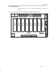


Loudspeaker Connectors (J100 . . . J800)
2-4
Table 2−5. J72 Pin Description
Pin No. Net-Name at Schematics Description
1 — Reserved for future use
2 V-HBRIDGE Sense of output power supply
3 GND Ground
4 RESET
System reset (bidirectional)
5
PSVC Power-supply volume control signal
2.2 Loudspeaker Connectors (J100 . . . J800)
Both positive and negative speaker outputs are floating and may
not be connected to ground (e.g., through an oscilloscope).
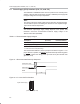
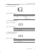
Figure 2−5. J100 . . . J800 Pin Numbers
1
2
(PCB connector top view)
Table 2−6. J100 . . . J800 Pin Description
Pin No. Net-Name at Schematics Description
1 OUT−1 Speaker negative output
2 OUT−2 Speaker positive output
2.3 Line Out Connectors (J950 and J951)
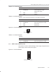
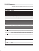
Figure 2−6. J950 and J951 Pin Numbers
(PCB connector top view)
2
3
4
1
Table 2−7. J950 and J952 Pin Description
Pin No. Net-Name at Schematics Description
1 GND Ground
2 OUT Line out signal
3 OUT Line out signal
4
OUT Line out signal