
Incor User's Guide Digital Amplifier TAS5518

www.ti.com
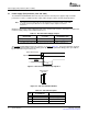
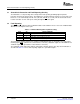
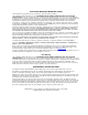
2.4 Headphone Connector (J700)
1
4
2 3
PCBConnector
(TopView)
2.5 Control Interface (J40)
Headphone Connector (J700)
Figure 2-5. J700 Pin Numbers
Table 2-6. J700 Pin Description
PIN NET NAME
DESCRIPTION
NO. AT SCHEMATICS
1 OUT-R Right headphone output
2 GND Ground
3 – Reserved
4 OUT-L Left headphone output
This interface connects the TAS5518-5152K8EVM board to a TI input-USB board.
Table 2-7. J40 Pin Description
NET NAME
PIN NO. DESCRIPTION
AT SCHEMATICS
1, 3, 11, 17,
GND Ground
25, 26, 31, 32
2, 8, 9,
13–16, 18, – Reserved
19, 27–30
4 RESET
Backend error (or soft reset). Provides reduced click and pop reset, without resetting I
2
C
5 BKND-ERR
volume register settings.
6 MUTE Ramp volume from any setting to noiseless soft mute. Mute also can be activated by I
2
C.
7 PDN Power down. The TAS5518 goes to power-down state when activated.
10 SDA I
2
C data clock
12 SCL I
2
C bit clock
Shutdown reporting. Activated if one or more TAS5152 has high current or high temperature
20 SD
(see Chapter 3 ).
Shutdown reporting. Activated if one or more TAS5152 has high current or high temperature
21 SD
Pin 21 connected to pin 20 (see Chapter 3 ).
Overtemperature warning. Activated if one or more TAS5152 has reached temperature
22 OTW
warning level.
Overtemperature warning. Activated if one or more TAS5152 has reached temperature
23 OTW
warning level. Pin 23 connected to pin 22.
Headphone select. Headphone active when LOW and inactive when HIGH. To use this pin, a
24 HP-SEL
100- Ω resistor must be placed for R50.
33, 34 5 V 5-V dc power supply (output)
SLEU074 – June 2006 System Interfaces 15
Submit Documentation Feedback