
Network Card User Manual

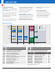

Interface Selection Guide Texas Instruments 4Q 2006
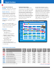
100 Mbps
200 Mbps
300 Mbps
400 Mbps
500 Mbps
600 Mbps
700 Mbps
Single Dual Quad 8-Channel 16-Channel
LVDM179
LVDM180
LVDM176
LVDM050
LVDM051
LVDM1676
LVDM1677
LVDM22
MLVD2
MLVD3
LVDM320
MLVD200A
MLVD202A
MLVD204A
MLVD205A
MLVD201
MLVD203
MLVD206
MLVD207
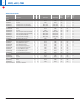
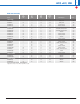
M-LVDS Transceivers
M-LVDS Clock Distribution
(see p.42 for table)
LVDM: a version of LVDS with
double the output current
M-LVDS Receivers
LVDM31
MLVD047
MLVD129
MLVD080
MLVD082
MLVD128
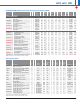
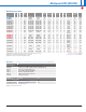
M-LVDS Features
• TIA/EIA-899 standard
• Driver output current
••
11.3 mA vs. 3.5 mA (LVDS)
• Receiver thresholds
••
50 mV vs. 100 mV (LVDS)
• Driver edge rate control
••
1 ns min allows ease-of-stub design
• Contention provisions
••
Driver short circuit limited to 43 mA
••
Drivers, receivers and disabled devices
must limit their bus voltage from
0 to 2.4 V
••
Drivers are tested with 32 contending
nodes
Multipoint LVDS
8
Multipoint-LVDS (M-LVDS)
➔
M-LVDS Devices from TI
• TIA/EIA-899 standard compliant
guarantees true multipoint
• Type 1 receivers: 25-mV hysteresis
to prevent oscillation
•
Type 2 receivers: internal failsafe
(no external bias network)
• –1-V to 3.4-V common mode
• 3.3-V supply operation
M-LVDS for ATCA
• Synchronous ATCA clock signals
(8 kHz, 19.22 MHz and user defined
<100 MHz) use M-LVDS.
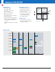
High
T
ype 1
Type 2
2.4 V
150 mV
50 mV
0 mV
–50 mV
High
Low
Transition Region
Low
V
I
D
2.4 V
Receiver types.