TNETX3270 ThunderSWITCH 24/3 ETHERNET SWITCH WITH 24 10-MBIT/S PORTS AND 3 10-/100-MBIT/S PORTS SPWS043B – NOVEMBER 1997 – REVISED APRIL 1999 D D D D Port Configurations: Twenty-Four 10-Mbit/s Ports – Ports Arranged in Three Groups of Eight Ports in a Multiplexed Interface – Direct Multiplexer Interface to TNETE2008 – Full and Half Duplex – Half-Duplex Collision-Based Flow Control – Full-Duplex IEEE Std 802.3x Flow Control – Interoperable Support for IEEE Std 802.
TNETX3270 ThunderSWITCH 24/3 ETHERNET SWITCH WITH 24 10-MBIT/S PORTS AND 3 10-/100-MBIT/S PORTS SPWS043B – NOVEMBER 1997 – REVISED APRIL 1999 description The TNETX3270 provides highly integrated switching solutions that allow network designers to lower overall system costs. Based on Texas Instruments (TI) ThunderSWITCH architecture, the TNETX3270 design integrates 24 full-duplex 10-Mbit/s ports and 3 full-duplex 10-/100-Mbit/s ports, as well as an address-lookup engine, all in a single 240-pin package.
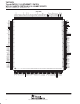
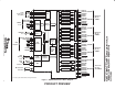
TNETX3270 ThunderSWITCH 24/3 ETHERNET SWITCH WITH 24 10-MBIT/S PORTS AND 3 10-/100-MBIT/S PORTS SPWS043B – NOVEMBER 1997 – REVISED APRIL 1999 Contents Description . . . . . . . . . . . . . . . . . . . . . . . . . . . . . . . . . . . . . . . . . . . 2 PGV Package Terminal Layout . . . . . . . . . . . . . . . . . . . . . . . . . . 4 TNETX3270 Interface Block Diagram . . . . . . . . . . . . . . . . . . . . 5 Terminal Functions . . . . . . . . . . . . . . . . . . . . . . . . . . . . . . . . . . . .
TNETX3270 ThunderSWITCH 24/3 ETHERNET SWITCH WITH 24 10-MBIT/S PORTS AND 3 10-/100-MBIT/S PORTS SPWS043B – NOVEMBER 1997 – REVISED APRIL 1999 180 179 178 177 176 175 174 173 172 171 170 169 168 167 166 165 164 163 162 161 160 159 158 157 156 155 154 153 152 151 150 149 148 147 146 145 144 143 142 141 140 139 138 137 136 135 134 133 132 131 130 129 128 127 126 125 124 123 122 121 DD25 DD24 V DD(2.5V) DD23 DD22 GND DD21 DD20 DD19 DD18 DD17 V DD(3.3V) DD16 DD15 DD14 V DD(2.5V) DD13 V DD(3.
Eight Ports (08–15) 10 Mbit/s TH2CLK TH2TXD3–TH2TXD0 TH2TXEN TH2COL TH2CRS TH2SYNC TH2RXD3–TH2RXD0 TH2RXDV TH2LINK TH2RENEG Eight Ports (16–23) 10 Mbit/s MxxTCLK MxxTXD3–MxxTXD0 MxxTXEN MxxTXER MxxCOL MxxCRS MxxRCLK MxxRXD3–MxxRXD0 MxxRXDV MxxRXER MxxFORCE10 MxxFORCEHD MxxLINK Three Ports (24–26)† 10/100 Mbit/s Controller (MAC) TAP Controller (MAC) Controller (MAC) Controller (MAC) Controller (MAC) Controller (MAC) SDRAM Controller Controller (MAC) Queue Manager Controller (MAC) Controller (MAC)
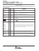
TNETX3270 ThunderSWITCH 24/3 ETHERNET SWITCH WITH 24 10-MBIT/S PORTS AND 3 10-/100-MBIT/S PORTS SPWS043B – NOVEMBER 1997 – REVISED APRIL 1999 Terminal Functions 10-Mbit/s MAC multiplexed interface (ports 00–23) is multiplexed into three groups (TH0, TH1, and TH2) of eight ports† TERMINAL NAME NO. I/O INTERNAL RESISTOR‡ DESCRIPTION TH0CLK TH1CLK TH2CLK 222 2 23 I Pullup Interface clock. Eight ports are supported on each interface and use this common 20-MHz clock.
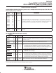
TNETX3270 ThunderSWITCH 24/3 ETHERNET SWITCH WITH 24 10-MBIT/S PORTS AND 3 10-/100-MBIT/S PORTS SPWS043B – NOVEMBER 1997 – REVISED APRIL 1999 Terminal Functions (Continued) 10-Mbit/s MAC multiplexed interface (ports 00–23) is multiplexed into three groups (TH0, TH1, and TH2) of eight ports† (continued) TERMINAL NAME NO.
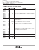
TNETX3270 ThunderSWITCH 24/3 ETHERNET SWITCH WITH 24 10-MBIT/S PORTS AND 3 10-/100-MBIT/S PORTS SPWS043B – NOVEMBER 1997 – REVISED APRIL 1999 Terminal Functions (Continued) 10-/100-Mbit/s MAC interface (ports 24–26) (continued)† TERMINAL NAME NO. I/O INTERNAL RESISTOR DESCRIPTION I Pullup Receive data (nibble receive data from the attached PHY or PMI device). Data on these signals is synchronous to MxxRCLK. MxxRXD0 is the least significant bit and MxxRXD3 is the most significant bit.
TNETX3270 ThunderSWITCH 24/3 ETHERNET SWITCH WITH 24 10-MBIT/S PORTS AND 3 10-/100-MBIT/S PORTS SPWS043B – NOVEMBER 1997 – REVISED APRIL 1999 Terminal Functions (Continued) SDRAM interface TERMINAL I/O INTERNAL RESISTOR DESCRIPTION 212 210 209 207 206 205 204 203 202 200 199 198 196 195 O None SDRAM address bus (time-multiplexed bank, row, and column address). The address bus DA13–DA00 also provides the SDRAM mode register initialization value.
TNETX3270 ThunderSWITCH 24/3 ETHERNET SWITCH WITH 24 10-MBIT/S PORTS AND 3 10-/100-MBIT/S PORTS SPWS043B – NOVEMBER 1997 – REVISED APRIL 1999 Terminal Functions (Continued) host DIO interface TERMINAL NAME NO. I/O INTERNAL RESISTOR DESCRIPTION SAD1 SAD0 143 142 I Pullup DIO address bus. SAD1 and SAD0 select the internal host registers, when SDMA is high. SCS 138 I Pullup DIO chip select. When low, SCS indicates a DIO port access is valid. Pullup DIO DMA select.
TNETX3270 ThunderSWITCH 24/3 ETHERNET SWITCH WITH 24 10-MBIT/S PORTS AND 3 10-/100-MBIT/S PORTS SPWS043B – NOVEMBER 1997 – REVISED APRIL 1999 Terminal Functions (Continued) serial MII management PHY interface TERMINAL I/O INTERNAL RESISTOR DESCRIPTION 121 O/High Z Pullup Serial MII management data clock. MDCLK can be disabled (high impedance) through the use of the SIO register. MDIO 120 I/O Pullup Serial MII management data I/O.
TNETX3270 ThunderSWITCH 24/3 ETHERNET SWITCH WITH 24 10-MBIT/S PORTS AND 3 10-/100-MBIT/S PORTS SPWS043B – NOVEMBER 1997 – REVISED APRIL 1999 Terminal Functions (Continued) miscellaneous TERMINAL I/O INTERNAL RESISTOR 112 I None Master system clock input (83.33-MHz input clock) 115 I None Reset. RESET is synchronous and, therefore, the system clock must be operational during reset. NAME NO. OSCIN RESET DESCRIPTION power interface TERMINAL NAME NO.
TNETX3270 ThunderSWITCH 24/3 ETHERNET SWITCH WITH 24 10-MBIT/S PORTS AND 3 10-/100-MBIT/S PORTS SPWS043B – NOVEMBER 1997 – REVISED APRIL 1999 DIO register groups Table 1.
TNETX3270 ThunderSWITCH 24/3 ETHERNET SWITCH WITH 24 10-MBIT/S PORTS AND 3 10-/100-MBIT/S PORTS SPWS043B – NOVEMBER 1997 – REVISED APRIL 1999 Table 2.
TNETX3270 ThunderSWITCH 24/3 ETHERNET SWITCH WITH 24 10-MBIT/S PORTS AND 3 10-/100-MBIT/S PORTS SPWS043B – NOVEMBER 1997 – REVISED APRIL 1999 Table 2.
TNETX3270 ThunderSWITCH 24/3 ETHERNET SWITCH WITH 24 10-MBIT/S PORTS AND 3 10-/100-MBIT/S PORTS SPWS043B – NOVEMBER 1997 – REVISED APRIL 1999 Table 2.
TNETX3270 ThunderSWITCH 24/3 ETHERNET SWITCH WITH 24 10-MBIT/S PORTS AND 3 10-/100-MBIT/S PORTS SPWS043B – NOVEMBER 1997 – REVISED APRIL 1999 Table 2.
TNETX3270 ThunderSWITCH 24/3 ETHERNET SWITCH WITH 24 10-MBIT/S PORTS AND 3 10-/100-MBIT/S PORTS SPWS043B – NOVEMBER 1997 – REVISED APRIL 1999 interface description DIO interface The DIO interface is a general-purpose interface that can be used with a wide range of microprocessor or computer systems. The interface supports external DMA controllers. This interface can be used to configure the TNETX3270 using an optional attached CPU (or EEPROM), and to access statistics registers.
TNETX3270 ThunderSWITCH 24/3 ETHERNET SWITCH WITH 24 10-MBIT/S PORTS AND 3 10-/100-MBIT/S PORTS SPWS043B – NOVEMBER 1997 – REVISED APRIL 1999 network management port Frames can be received or transmitted via the DIO interface using a built-in port, the network management (NM) port. Frames originating within the host are written to this port via the NMRxcontrol and NMdata registers. Once a frame has been fully written, it is then received by the switch and routed to the destination port(s).
TNETX3270 ThunderSWITCH 24/3 ETHERNET SWITCH WITH 24 10-MBIT/S PORTS AND 3 10-/100-MBIT/S PORTS SPWS043B – NOVEMBER 1997 – REVISED APRIL 1999 frame format on the NM port The frame format on the NM port differs slightly from a standard Ethernet frame format. The key differences are: the frame always contains an IEEE Std 802.1Q header in the four bytes following the source address (see Figure 2).
TNETX3270 ThunderSWITCH 24/3 ETHERNET SWITCH WITH 24 10-MBIT/S PORTS AND 3 10-/100-MBIT/S PORTS SPWS043B – NOVEMBER 1997 – REVISED APRIL 1999 frame format on the NM port (continued) TPID (Tag Protocol Identifier) TCI (Tag Control Information) 1 0 0 0 0 0 0 1 0 0 0 0 0 0 0 0 Priority cfi VLAN ID 7 6 5 4 3 2 1 0 7 6 5 4 3 2 1 0 7 6 5 4 3 2 1 0 7 6 5 4 3 2 1 0 802.
TNETX3270 ThunderSWITCH 24/3 ETHERNET SWITCH WITH 24 10-MBIT/S PORTS AND 3 10-/100-MBIT/S PORTS SPWS043B – NOVEMBER 1997 – REVISED APRIL 1999 frame format on the NM port (continued) When a frame is transmitted on the NM port, no header stripping occurs (again because the NM port does not have a PortxQtag register or txacc bit), so the frame read by the host software contains one header (or possibly more, depending on how the frame was received).
TNETX3270 ThunderSWITCH 24/3 ETHERNET SWITCH WITH 24 10-MBIT/S PORTS AND 3 10-/100-MBIT/S PORTS SPWS043B – NOVEMBER 1997 – REVISED APRIL 1999 receive filtering of frames Received frames that contain an error (e.g., CRC, alignment, jabber, etc.) are discarded before transmission and the relevant statistics counter is updated. data transmission The MAC takes data from the TNETX3270 internal buffer memory and passes it to the PHY. The data also is synchronized to the transmit clock rate.
TNETX3270 ThunderSWITCH 24/3 ETHERNET SWITCH WITH 24 10-MBIT/S PORTS AND 3 10-/100-MBIT/S PORTS SPWS043B – NOVEMBER 1997 – REVISED APRIL 1999 receive versus transmit priority The queue manager prioritizes receive and transmit traffic as follows: D D D D Highest priority is given to frames that currently are being transmitted. This ensures that transmitting frames do not underrun. Next priority is given to frames that are received if the free-buffer stack is not empty.
TNETX3270 ThunderSWITCH 24/3 ETHERNET SWITCH WITH 24 10-MBIT/S PORTS AND 3 10-/100-MBIT/S PORTS SPWS043B – NOVEMBER 1997 – REVISED APRIL 1999 Table 5.
TNETX3270 ThunderSWITCH 24/3 ETHERNET SWITCH WITH 24 10-MBIT/S PORTS AND 3 10-/100-MBIT/S PORTS SPWS043B – NOVEMBER 1997 – REVISED APRIL 1999 port-routing-code pretag on reception If the pretag bit is set to 1 in the appropriate Portxcontrol register, during the seven MxxRCLK cycles prior to MxxRXDV going high, the port expects to receive a seven-nibble pretag on MxxRXD3–MxxRXD0 (see Figure 4).
TNETX3270 ThunderSWITCH 24/3 ETHERNET SWITCH WITH 24 10-MBIT/S PORTS AND 3 10-/100-MBIT/S PORTS SPWS043B – NOVEMBER 1997 – REVISED APRIL 1999 EEPROM interface The EEPROM interface is provided so the system-level manufacturer can produce a CPU-less, preconfigured system to their customers. Customers also may want to change or reconfigure their system and retain their preferences between system power downs. The device cannot be used without either an EEPROM or CPU connected to it (see Figure 5).
TNETX3270 ThunderSWITCH 24/3 ETHERNET SWITCH WITH 24 10-MBIT/S PORTS AND 3 10-/100-MBIT/S PORTS SPWS043B – NOVEMBER 1997 – REVISED APRIL 1999 EEPROM interface (continued) Multiple bus masters are not supported on the EEPROM interface because the ECLK pin always is driven by the device with a strong 0/strong 1 (i.e., not a strong 1/resistively pulled-up 1). An Ethernet CRC check is used to ensure the EEPROM data is valid.
TNETX3270 ThunderSWITCH 24/3 ETHERNET SWITCH WITH 24 10-MBIT/S PORTS AND 3 10-/100-MBIT/S PORTS SPWS043B – NOVEMBER 1997 – REVISED APRIL 1999 JTAG interface The TNETX3270 is fully IEEE Std 1149.1 compliant. It also includes on-chip pullup resistors on the five JTAG terminals to eliminate the need for external ones. All JTAG inputs and outputs are 3.3-V tolerant.
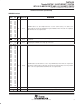
TNETX3270 ThunderSWITCH 24/3 ETHERNET SWITCH WITH 24 10-MBIT/S PORTS AND 3 10-/100-MBIT/S PORTS SPWS043B – NOVEMBER 1997 – REVISED APRIL 1999 Table 10. LED Status Bit Definitions and Shift Order ORDER slast = 0 slast = 1 1–7 1–7 8–19 35–46 NAME 0 FUNCTION Zero. Dummy data for first seven of 48 LEDCLK cycles. SW0–SW11 Software LEDs 0–11. These allow additional software-controlled status to be displayed.
TNETX3270 ThunderSWITCH 24/3 ETHERNET SWITCH WITH 24 10-MBIT/S PORTS AND 3 10-/100-MBIT/S PORTS SPWS043B – NOVEMBER 1997 – REVISED APRIL 1999 Table 11.
TNETX3270 ThunderSWITCH 24/3 ETHERNET SWITCH WITH 24 10-MBIT/S PORTS AND 3 10-/100-MBIT/S PORTS SPWS043B – NOVEMBER 1997 – REVISED APRIL 1999 PORT 0 1 2 3 4 5 6 7 0 1 M00TXD M01TXD M02TXD M03TXD M04TXD M05TXD M06TXD M07TXD M00TXD M01TXD CLK SYNC TXD3TXD0 TXEN M00TXEN M01TXEN M02TXEN M03TXEN M04TXEN M05TXEN M06TXEN M07TXEN M00TXEN M01TXEN FORCEHD M00FHD M01FHD M02FHD M03FHD M04FHD M05FHD M06FHD M07FHD M00FHD M01FHD COL M02COL M03COL M04COL M05COL M06COL M07COL M00
TNETX3270 ThunderSWITCH 24/3 ETHERNET SWITCH WITH 24 10-MBIT/S PORTS AND 3 10-/100-MBIT/S PORTS SPWS043B – NOVEMBER 1997 – REVISED APRIL 1999 THxCLK (input) Clock Runs Continuously THxTXEN (output) THxTXD3 (output) Must be 0 THxTXD2 (output) Must be 0 THxTXD1 (output) Pause (0 = no pause) THxTXD0 (output) THxLINK (input) (1 = pause requested) Half Duplex (0 = full duplex) (1 = half duplex) TNETE2008 latches final values, just before autonegotiation the fast-link pulse exchange begins.
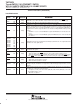
TNETX3270 ThunderSWITCH 24/3 ETHERNET SWITCH WITH 24 10-MBIT/S PORTS AND 3 10-/100-MBIT/S PORTS SPWS043B – NOVEMBER 1997 – REVISED APRIL 1999 10-/100-Mbit/s MAC interfaces (ports 24–26) Unlike the 10-Mbit/s ports, each 10-/100-Mbit/s port has a dedicated set of signals to interface to its PHY. Table 12 shows how a TNETE2101 10-/100-Mbit/s PHY would be connected to one of the 10-/100-Mbit/s ports of TNETX3270. Table 12.
TNETX3270 ThunderSWITCH 24/3 ETHERNET SWITCH WITH 24 10-MBIT/S PORTS AND 3 10-/100-MBIT/S PORTS SPWS043B – NOVEMBER 1997 – REVISED APRIL 1999 10-/100-Mbit/s port configuration (continued) Each terminal is considered to be bidirectional, when pulled low by either TNETX3270 or by the PHY (or other external connections). If neither pulls the terminal low, then the pullup resistor maintains a value of 1 on the terminal.
TNETX3270 ThunderSWITCH 24/3 ETHERNET SWITCH WITH 24 10-MBIT/S PORTS AND 3 10-/100-MBIT/S PORTS SPWS043B – NOVEMBER 1997 – REVISED APRIL 1999 10-/100-Mbit/s port configuration in a managed switch The 10-/100-Mbit/s ports can be configured in a managed switch using either of the following procedures: 1. The management CPU sets the req10 and reqhd bits of the Portxcontrol registers as required while the PHYs are held in reset.
TNETX3270 ThunderSWITCH 24/3 ETHERNET SWITCH WITH 24 10-MBIT/S PORTS AND 3 10-/100-MBIT/S PORTS SPWS043B – NOVEMBER 1997 – REVISED APRIL 1999 SDRAM interface (continued) Table 15.
TNETX3270 ThunderSWITCH 24/3 ETHERNET SWITCH WITH 24 10-MBIT/S PORTS AND 3 10-/100-MBIT/S PORTS SPWS043B – NOVEMBER 1997 – REVISED APRIL 1999 SDRAM-type and quantity indication Before beginning operation (by writing to the start bit of Syscontrol), it is necessary to indicate to the SDRAM interface whether × 8 or × 16 SDRAMs are being used. This is done by setting the bit in the RAMsize register (by 8 = 0 for × 16, by 8 = 1 for × 8) during the load from EEPROM or via a DIO write.
TNETX3270 ThunderSWITCH 24/3 ETHERNET SWITCH WITH 24 10-MBIT/S PORTS AND 3 10-/100-MBIT/S PORTS SPWS043B – NOVEMBER 1997 – REVISED APRIL 1999 frame routing VLAN support The internal routing engine supports the IEEE Std 802.1Q VLANs as shown in Figure 8 and described in the following paragraphs. Receive IEEE Std 802.1Q Format Frame Header If rxacc = 1 Header Inserted If VLAN ID = 0x000 VLAN ID Replaced Record Number NonIEEE Std 802.
TNETX3270 ThunderSWITCH 24/3 ETHERNET SWITCH WITH 24 10-MBIT/S PORTS AND 3 10-/100-MBIT/S PORTS SPWS043B – NOVEMBER 1997 – REVISED APRIL 1999 IEEE Std 802.1Q headers – reception When the internal address-lookup engine (IALE) examines the received frame, it contains an IEEE Std 802.1Q header (after the source address). The header used depends on the port configuration. If the port is configured as an access port, then IALE always uses the default VLAN ID (VID) programmed for this port.
TNETX3270 ThunderSWITCH 24/3 ETHERNET SWITCH WITH 24 10-MBIT/S PORTS AND 3 10-/100-MBIT/S PORTS SPWS043B – NOVEMBER 1997 – REVISED APRIL 1999 spanning-tree support Each port provides independent controls to block reception or transmission of frames, for learning of addresses, or to disable the port on a per-port basis. Blocking can be overridden to allow reception or transmission of spanning-tree frames.
TNETX3270 ThunderSWITCH 24/3 ETHERNET SWITCH WITH 24 10-MBIT/S PORTS AND 3 10-/100-MBIT/S PORTS SPWS043B – NOVEMBER 1997 – REVISED APRIL 1999 Start Key: UnkVLAN No Known VLAN? interrupt statistic Yes Unkmem No Source Port = 1 in. VLANnports? Yes Yes Yes Destination Locked Bit = 1? No No Yes Destination Address Found? Destination is Multicast? Destination is Multicast? Yes Source Port Blocked by RxUniBlockPorts and Dest.
TNETX3270 ThunderSWITCH 24/3 ETHERNET SWITCH WITH 24 10-MBIT/S PORTS AND 3 10-/100-MBIT/S PORTS SPWS043B – NOVEMBER 1997 – REVISED APRIL 1999 A B Source Address Found? No Source Port = 1 in NLearnPorts? new No Yes Yes Source Locked Bit = 1? No Source Port Moved? No Yes Yes Unknown Source secvio Source Secure Bit = 1? Yes Source Port Security Violation Discard Frame No No chng AND UnkSrcPorts With VLAN VLANnports, Then OR With Port Routing Code Stayed Within a Trunk? Yes Yes Source
TNETX3270 ThunderSWITCH 24/3 ETHERNET SWITCH WITH 24 10-MBIT/S PORTS AND 3 10-/100-MBIT/S PORTS SPWS043B – NOVEMBER 1997 – REVISED APRIL 1999 C E D Remove: – Disabled Ports – Ports Blocked by TxBlockPorts From Port Routing Code If Mirr Bit = 1? Yes ((Source Port = MirrorPort or Port Routing Code Includes MirrorPort) and (Source Port ! = UplinkPort)) Then Include UplinkPort in Port Routing Code No Lshare = 1? Yes No Yes Port Routing Code is Adjusted by Trunking Algorithm (see Note A) Port Rou
TNETX3270 ThunderSWITCH 24/3 ETHERNET SWITCH WITH 24 10-MBIT/S PORTS AND 3 10-/100-MBIT/S PORTS SPWS043B – NOVEMBER 1997 – REVISED APRIL 1999 port trunking/load sharing Port trunking is a technique that allows two or more ports to be parallel connected between switches and counted as one port to increase the bandwidth between those devices. The trunking algorithm determines on which of these ports a frame is transmitted, spreading the load evenly across these ports and maintaining packet order.
TNETX3270 ThunderSWITCH 24/3 ETHERNET SWITCH WITH 24 10-MBIT/S PORTS AND 3 10-/100-MBIT/S PORTS SPWS043B – NOVEMBER 1997 – REVISED APRIL 1999 collision-based flow control Collision-based flow control provides a means of preventing frame reception for ports that are operating in half-duplex mode. While the number of free buffers is fewer than the specified threshold, ports in this state that are not currently transmitting generate collisions when they start to receive a frame.
TNETX3270 ThunderSWITCH 24/3 ETHERNET SWITCH WITH 24 10-MBIT/S PORTS AND 3 10-/100-MBIT/S PORTS SPWS043B – NOVEMBER 1997 – REVISED APRIL 1999 pause frame reception The IEEE Std 802.3X standard defines a MAC control frame as any frame containing a length/type value = 88.08 (hex). This device always absorbs (i.e., discards) within the MAC all such frames that it receives, regardless of the configuration of the port (i.e., pause and duplex have no effect on this behavior).
TNETX3270 ThunderSWITCH 24/3 ETHERNET SWITCH WITH 24 10-MBIT/S PORTS AND 3 10-/100-MBIT/S PORTS SPWS043B – NOVEMBER 1997 – REVISED APRIL 1999 pause frame transmission (continued) Pause frames are transmitted if required, even if the port is observing the pausetime period from a pause frame it has received. internal wrap test Internal wrap mode causes some or all of the Ethernet MACs to be configured to loop back transmitted data into the receive path.
TNETX3270 ThunderSWITCH 24/3 ETHERNET SWITCH WITH 24 10-MBIT/S PORTS AND 3 10-/100-MBIT/S PORTS SPWS043B – NOVEMBER 1997 – REVISED APRIL 1999 08 09 26 07 06 NM TNETX3270 05 04 03 02 01 00 Figure 10. Internal Wrap Example duplex wrap test Duplex wrap test is similar to internal wrap mode (see Figure 11). The ports can be set to accept frame data that is wrapped at the PHY. This permits network connections between the device and the PHY to be verified.
TNETX3270 ThunderSWITCH 24/3 ETHERNET SWITCH WITH 24 10-MBIT/S PORTS AND 3 10-/100-MBIT/S PORTS SPWS043B – NOVEMBER 1997 – REVISED APRIL 1999 port mirroring It is possible to copy (or mirror) all frames that are received by and transmitted to a port designated by the Mirrorport register to the port designated by the Uplinkport register. This feature is enabled if the mirr bit in Syscontrol is set to 1, and disabled if it is 0.
TNETX3270 ThunderSWITCH 24/3 ETHERNET SWITCH WITH 24 10-MBIT/S PORTS AND 3 10-/100-MBIT/S PORTS SPWS043B – NOVEMBER 1997 – REVISED APRIL 1999 absolute maximum ratings over operating junction temperature range (unless otherwise noted)† Supply voltage range: VDD(2.5V) . . . . . . . . . . . . . . . . . . . . . . . . . . . . . . . . . . . . . . . . . . . . . . . . . . . –0.5 V to 2.7 V VDD(3.3V) . . . . . . . . . . . . . . . . . . . . . . . . . . . . . . . . . . . . . . . . . . . . . . . . . . . –0.5 V to 3.
TNETX3270 ThunderSWITCH 24/3 ETHERNET SWITCH WITH 24 10-MBIT/S PORTS AND 3 10-/100-MBIT/S PORTS SPWS043B – NOVEMBER 1997 – REVISED APRIL 1999 PARAMETER MEASUREMENT INFORMATION Outputs are driven to a minimum high-logic level of 3.3 V and to a maximum low-logic level of 0 V. Output transition times are specified as follows: For a high-to-low transition on either an input or output signal, the level at which the signal is said to be no longer high is 1.
TNETX3270 ThunderSWITCH 24/3 ETHERNET SWITCH WITH 24 10-MBIT/S PORTS AND 3 10-/100-MBIT/S PORTS SPWS043B – NOVEMBER 1997 – REVISED APRIL 1999 10-Mbit/s interface (ports 00–23) timing requirements (see Notes 3 through 6 and Figure 13) NO.
TNETX3270 ThunderSWITCH 24/3 ETHERNET SWITCH WITH 24 10-MBIT/S PORTS AND 3 10-/100-MBIT/S PORTS SPWS043B – NOVEMBER 1997 – REVISED APRIL 1999 1 THxCLK (input) 2 2 THxSYNC (input) 3 THxCOL THxCRS THxLINK THxRXD3–THxRXD0 THxRXDV (inputs) 5 4 6 7 THxTXEN THxTXD3–THxTXD0 THxRENEG (outputs) 8 Figure 13. 10-Mbit/s Interface (Ports 00–23) 10-/100-Mbit/s MAC interface Figures 14 and 15 show the timings at 100 Mbit/s and 10 Mbit/s for the 10-/100-Mbit/s port interfaces to the TNETE2101 devices.
TNETX3270 ThunderSWITCH 24/3 ETHERNET SWITCH WITH 24 10-MBIT/S PORTS AND 3 10-/100-MBIT/S PORTS SPWS043B – NOVEMBER 1997 – REVISED APRIL 1999 10-/100-Mbit/s transmit ports (24, 25, and 26) timing requirements (see Figure 15) NO. 1 Cycle time, MxxTCLK 2 tc(MxxTCLK) tw(MxxTCLKL) 3 tw(MxxTCLKH) Pulse duration, MxxTCLK high MIN MAX 25 25 Pulse duration, MxxTCLK low UNIT ns ns 14 ns operating characteristics over recommended operating conditions (see Note 8 and Figure 15) NO.
TNETX3270 ThunderSWITCH 24/3 ETHERNET SWITCH WITH 24 10-MBIT/S PORTS AND 3 10-/100-MBIT/S PORTS SPWS043B – NOVEMBER 1997 – REVISED APRIL 1999 SDRAM interface The SDRAM interface observes two types of timing: D D Multicycle timings between commands Subcycle timings between signals and DCLK Figure 16 illustrates the SDRAM interfaces signal timing in which each type of SDRAM command and its interrelated timings are shown.
TNETX3270 ThunderSWITCH 24/3 ETHERNET SWITCH WITH 24 10-MBIT/S PORTS AND 3 10-/100-MBIT/S PORTS SPWS043B – NOVEMBER 1997 – REVISED APRIL 1999 SDRAM subcycle operating characteristics over recommended operating conditions (see Figure 17) NO.
TNETX3270 ThunderSWITCH 24/3 ETHERNET SWITCH WITH 24 10-MBIT/S PORTS AND 3 10-/100-MBIT/S PORTS SPWS043B – NOVEMBER 1997 – REVISED APRIL 1999 DIO/DMA interface The DIO interface is asynchronous to allow easy adaptation to a range of microprocessor devices and computer system interfaces. DIO/DMA write cycle timing requirements (see Figure 18) NO.
TNETX3270 ThunderSWITCH 24/3 ETHERNET SWITCH WITH 24 10-MBIT/S PORTS AND 3 10-/100-MBIT/S PORTS SPWS043B – NOVEMBER 1997 – REVISED APRIL 1999 DIO/DMA read cycle timing requirements (see Figure 19) NO.
TNETX3270 ThunderSWITCH 24/3 ETHERNET SWITCH WITH 24 10-MBIT/S PORTS AND 3 10-/100-MBIT/S PORTS SPWS043B – NOVEMBER 1997 – REVISED APRIL 1999 serial MII management interface timing requirements (see Figure 20) NO. 1 MIN tsu(MDIO) th(MDIO) 2 MAX UNIT Setup time, MDIO valid before OSCIN↑, read 7 ns Hold time, MDIO valid after OSCIN↑, read 3 ns operating characteristics over recommended operating conditions (see Figure 20) NO.
TNETX3270 ThunderSWITCH 24/3 ETHERNET SWITCH WITH 24 10-MBIT/S PORTS AND 3 10-/100-MBIT/S PORTS SPWS043B – NOVEMBER 1997 – REVISED APRIL 1999 EEPROM interface operating characteristics over recommended operating conditions (see Figure 21) NO NO.
TNETX3270 ThunderSWITCH 24/3 ETHERNET SWITCH WITH 24 10-MBIT/S PORTS AND 3 10-/100-MBIT/S PORTS SPWS043B – NOVEMBER 1997 – REVISED APRIL 1999 LED interface operating characteristics over recommended operating conditions (see Figure 22) NO.
TNETX3270 ThunderSWITCH 24/3 ETHERNET SWITCH WITH 24 10-MBIT/S PORTS AND 3 10-/100-MBIT/S PORTS SPWS043B – NOVEMBER 1997 – REVISED APRIL 1999 power-up OSCIN and RESET timing requirements (see Figure 23) NO. MIN NOM Frequency drift, OSCIN clock 1 MAX UNIT ±50 ppm tc(OSCIN) tw(OSCINL) Cycle time, OSCIN Pulse duration, OSCIN low 4.8 7.2 ns tw(OSCINH) tw(RESET) Pulse duration, OSCIN high 4.8 7.
TNETX3270 ThunderSWITCH 24/3 ETHERNET SWITCH WITH 24 10-MBIT/S PORTS AND 3 10-/100-MBIT/S PORTS SPWS043B – NOVEMBER 1997 – REVISED APRIL 1999 MECHANICAL DATA PGV (S-PQFP-G240) PLASTIC QUAD FLATPACK (DIE–DOWN) 180 121 120 181 Heat Slug 0,27 0,17 0,08 M 0,50 0,16 NOM 240 61 1 60 Gage Plane 29,50 TYP 0,25 32,20 SQ 31,80 0,25 MIN 0,75 0,50 34,80 SQ 34,40 0°– 7° 3,80 TYP Seating Plane 0,08 4,20 MAX 4040247 / A 03/95 NOTES: A. All linear dimensions are in millimeters. B.
IMPORTANT NOTICE Texas Instruments and its subsidiaries (TI) reserve the right to make changes to their products or to discontinue any product or service without notice, and advise customers to obtain the latest version of relevant information to verify, before placing orders, that information being relied on is current and complete.