
Switch User Manual

TNETX3270
ThunderSWITCH 24/3 ETHERNET SWITCH
WITH 24 10-MBIT/S PORTS AND 3 10-/100-MBIT/S PORTS
SPWS043B – NOVEMBER 1997 – REVISED APRIL 1999
12
POST OFFICE BOX 655303 • DALLAS, TEXAS 75265
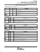
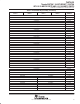
Terminal Functions (Continued)
miscellaneous
TERMINAL
I/O
INTERNAL
DESCRIPTION
NAME NO.
I/O
RESISTOR
DESCRIPTION
OSCIN
112 I None Master system clock input (83.33-MHz input clock)
RESET
115 I None Reset. RESET is synchronous and, therefore, the system clock must be operational during reset.
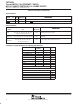
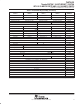
power interface
TERMINAL
INTERNAL
DESCRIPTION
NAME NO.
RESISTOR
DESCRIPTION
GND
8, 14, 34, 40, 55, 68, 74, 81, 88, 94, 100,
128, 134, 141, 148, 154, 160, 175, 188,
194, 201, 208, 214, 220, 235
None
Ground. GND is the 0-V reference for the device. All GND
terminals must be connected.
V
DD(3.3V)
12, 72, 109, 122, 132, 163, 169, 192, 229 None
3.3-V supply voltage. Power for the input, output, and I/O
terminals.
V
DD(2.5V)
4, 17, 31, 45, 58, 64, 77, 91,
105, 118, 124, 137, 151, 165, 178,
184, 197, 211, 225, 238
None 2.5-V supply voltage. Power for the core.
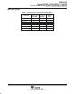
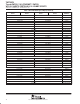
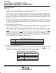
summary of signal terminals by signal group function
PORT DESCRIPTION
NUMBER OF
SIGNALS
MULTIPLIER TOTAL
LED 2 1 2
10-Mbit/s port 16 3 48
10-/100-Mbit/s port 19 3 57
DIO 17 1 17
EEPROM interface 2 1 2
DRAM interface 50 1 50
Miscellaneous 2 1 2
JTAG 5 1 5
Serial MII management 3 1 3
Total signals 186
SUMMARY
Assigned terminals 186
V
DD(3.3V)
9
V
DD(2.5V)
20
GND 25
Total terminals 240