
Switch User Manual

TNETX3270
ThunderSWITCH 24/3 ETHERNET SWITCH
WITH 24 10-MBIT/S PORTS AND 3 10-/100-MBIT/S PORTS
SPWS043B – NOVEMBER 1997 – REVISED APRIL 1999
37
POST OFFICE BOX 655303 • DALLAS, TEXAS 75265
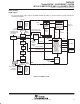
SDRAM interface (continued)
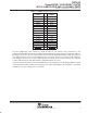
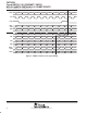
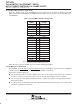
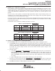
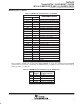
Table 15. TNETX3270 Terminal Interface to SDRAMs
TERMINALS
SDRAM TERMINAL FUNCTION
TNETX3270 SDRAM
SDRAM
TERMINAL
FUNCTION
DA13 A13 Row/bank address (64-M SDRAMs only)
DA12 A12 Row/bank address (64-M SDRAMs only)
DA11 A11 Row/bank address
DA10 A10 Row address/auto-precharge select
DA09 A9 Row address
DA08 A8 Row address/column address (× 8 only)
DA07 A7 Row address/column address
DA06 A6 Row address/column address
DA05 A5 Row address/column address
DA04 A4 Row address/column address
DA03 A3 Row address/column address
DA02 A2 Row address/column address
DA01 A1 Row address/column address
DA00 A0 Row address/column address
DRAS RAS Row address strobe
DCAS CAS Column address strobe
DW W Write enable
DCLK CLK Clock
DD31–DD16 DQ15–DQ0 SDRAM1. Data I/O (× 16 SDRAMs)
DD15–DD00 DQ15–DQ0 SDRAM0
DD31–DD24 DQ7–DQ0 SDRAM3. Data I/O (× 8 SDRAMs)
DD23–DD16 DQ7–DQ0 SDRAM2
DD15–DD08 DQ7–DQ0 SDRAM1
DD07–DD00 DQ7–DQ0 SDRAM0
DA13 and DA12 should be left unconnected if 16M-bit SDRAMs are used. The remaining functional SDRAM
terminals that are not directly controlled by the SDRAM interface should be tied off from the external system
during operation (see Table 16).
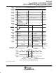
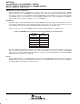
Table 16. SDRAM Terminals Not Driven by the TNETX3270
HELD
SDRAM
TERMINAL
SDRAM
TERMINAL FUNCTION
Low CS Chip select
High CKE CLK enable
Low DQM Data mask (× 8 SDRAMs)
Low DQML Data mask (× 16 SDRAMs)
Low DQMU Data mask (× 16 SDRAMs)