
Datasheet

www.ti.com
FEATURES
1
2
3
4
8
7
6
5
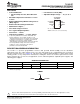
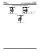
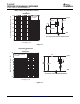
CATHODE
ANODE
ANODE
NC
REF
ANODE
ANODE
NC
JG PACKAGE
(TOP VIEW)
NC − No internal connection
ANODE terminals are connected internally.
DESCRIPTION/ORDERING INFORMATION
REF
ANODE
CATHODE
TL1431-EP
PRECISION PROGRAMMABLE REFERENCE
SLVS529C – APRIL 2004 – REVISED DECEMBER 2006
• Controlled Baseline • Low Reference Current (REF)
– One Assembly/Test Site, One Fabrication • Adjustable Output Voltage . . . V
I(ref)
to 36 V
Site
• Extended Temperature Performance of –55 ° C
to 125 ° C
• Enhanced Diminishing Manufacturing Sources
(DMS) Support
• Enhanced Product-Change Notification
• Qualification Pedigree
(1)
• 0.4% Initial Voltage Tolerance
• 0.2- Ω Typical Output Impedance
• Fast Turnon . . . 500 ns
• Sink Current Capability . . . 1 mA to 100 mA
(1) Component qualification in accordance with JEDEC and
industry standards to ensure reliable operation over an
extended temperature range. This includes, but is not limited
to, Highly Accelerated Stress Test (HAST) or biased 85/85,
temperature cycle, autoclave or unbiased HAST,
electromigration, bond intermetallic life, and mold compound
life. Such qualification testing should not be viewed as
justifying use of this component beyond specified
performance and environmental limits.
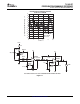
The TL1431 is a precision programmable reference with specified thermal stability over the automotive
temperature range. The output voltage can be set to any value between V
I(ref)
(approximately 2.5 V) and 36 V
with two external resistors (see Figure 16 ). This device has a typical output impedance of 0.2 Ω . Active output
circuitry provides a very sharp turnon characteristic, making the device an excellent replacement for Zener
diodes and other types of references in applications such as onboard regulation, adjustable power supplies, and
switching power supplies.
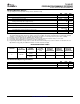
ORDERING INFORMATION
T
A
PACKAGE
(1)
ORDERABLE PART NUMBER TOP-SIDE MARKING
–40 ° C to 125 ° C SOIC – D Reel of 2500 TL1431QDREP 1431QE
–55 ° C to 125 ° C SOIC – D Reel of 2500 TL1431MDREP 1431ME
(1) Package drawings, standard packing quantities, thermal data, symbolizatin, and PCB design guidelines are available at
www.ti.com/sc/package.
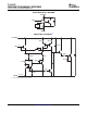
SYMBOL
Please be aware that an important notice concerning availability, standard warranty, and use in critical applications of Texas
Instruments semiconductor products and disclaimers thereto appears at the end of this data sheet.
PRODUCTION DATA information is current as of publication date.
Copyright © 2004–2006, Texas Instruments Incorporated
Products conform to specifications per the terms of the Texas
Instruments standard warranty. Production processing does not
necessarily include testing of all parameters.