
Datasheet
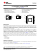
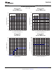
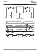

KTT (TO-263-5) Package
(Top View)
OUT
RESET
RESET
GND
DELAY
DELAY
IN
GND
1
1
2
2
3
3
4
4
5
5
4
5
6
7
8
9
10
20
19
18
17
16
15
14
13
12
11
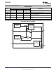
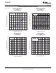
RESET
NC
DELAY
OUT
NC
NC
NC
GND
Thermal
Pad
NC
NC
NC
IN
NC
NC
NC
NC
NC
NC
NC
NC
PWP (HTSSOP) Package
(Top View)
OUT
GND
IN
GND
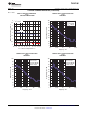
KVU (TO-252-5) Package
(Top View)
1
2
3
TLE4275-Q1
www.ti.com
SLVS647H –AUGUST 2006–REVISED MARCH 2013
5-V LOW-DROPOUT VOLTAGE REGULATOR
Check for Samples: TLE4275-Q1
1
FEATURES
• Qualified for Automotive Applications • Reset Low-Level Output Voltage < 1 V
• Output Voltage 5 V ± 2% • Very Low Dropout Voltage
• Very Low Current Consumption • Short-Circuit Proof
• Power-On and Undervoltage Reset • Reverse-Polarity Proof
DESCRIPTION
The TLE4275 is a monolithic integrated low-dropout voltage regulator offered in a 5-pin TO package. The device
regulates an input voltage up to 45 V to V
OUT
= 5 V (typ). The device can drive loads up to 450 mA and is short-
circuit proof. At overtemperature, the incorporated temperature protection turns off the TLE4275. The device
generates a reset signal for an output voltage, V
OUT,rt
, of 4.65 V (typ). By the use of an external delay capacitor,
one can program the reset delay time.
The input capacitor, C
IN
, compensates for line fluctuation. Using a resistor of approximately 1 Ω in series with C
IN
dampens the oscillation of input inductance and input capacitance. The output capacitor, C
OUT
, stabilizes the
regulation circuit. The specification for stability is at C
OUT
≥ 22 μF and ESR ≤ 5 Ω, within the operating
temperature range. Stability for electrolytic capacitors specifically is at C
OUT
≥ 68 µF within the operating
temperature range. See the application report on low-temperature stability, SLVA501, for further details.
The control amplifier compares a reference voltage to a voltage that is proportional to the output voltage and
drives the base of the series transistor via a buffer. Saturation control as a function of the load current prevents
any oversaturation of the power element. The device also incorporates a number of internal circuits for protection
against:
• Overload
• Overtemperature
• Reverse polarity
ORDERING INFORMATION
For the most current package and ordering information, see the Package Option Addendum at the end of this
document, or see the TI Web site at www.ti.com.
Package drawings, thermal data, and symbolization are available at www.ti.com/packaging.
1
Please be aware that an important notice concerning availability, standard warranty, and use in critical applications of
Texas Instruments semiconductor products and disclaimers thereto appears at the end of this data sheet.
UNLESS OTHERWISE NOTED this document contains
Copyright © 2006–2013, Texas Instruments Incorporated
PRODUCTION DATA information current as of publication date.
Products conform to specifications per the terms of Texas
Instruments standard warranty. Production processing does not
necessarily include testing of all parameters.