
TV Converter Box User Manual

Appendix A EVM Connector Descriptions
A.1 Analog Interface Connectors
A.1.1 Analog Input/Output Connectors
Appendix A
www.ti.com
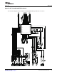
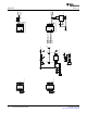
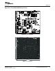
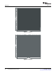
This appendix contains the connection details for each of the main header connectors on the EVM.
In addition to the analog headers, the analog inputs and outputs also can be accessed through alternate
connectors, either screw terminals or audio jacks. The stereo microphone input is also tied to J6 and the
stereo headphone output (the HP set of outputs) is available at J7.
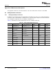
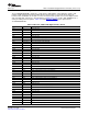
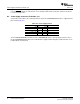
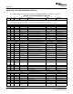
Table A-1 summarizes the analog input/output connectors available for Block A.
Table A-1. Analog Input/Output Connectors
Designator Description Function PIN 1 PIN 2 PIN3
J6 3-Conductor Screw See SW1 Configuration for LINE1LP AGND LINE1LM
Terminal Input SE/Diff Usage
J7 3-Conductor Screw See SW1 Configuration for LINE1RP AGND LINE1RM
Terminal Input SE/Diff Usage
J8 3-Conductor Screw See SW1 Configuration for LINE2LP AGND LINE2LM
Terminal Input SE/Diff Usage
J9 Audio 3.5mm Stereo Input External Mic Input (See SW1 AGND MIC3L MIC3R
Jack Configuration)
J10 Audio 3.5mm Stereo Headset Output (See SW2 AGND HPLOUT HPROUT
Output Jack Configuration)
J11 Audio 3.5mm Stereo Headset Test Output (See AGND HPL-TEST HPR-TEST
Output Jack SW2 Configuration) (filtered) (filtered)
J12 3-Conductor Screw Lineout LEFT_LOP AGND RIGHT_LOP
Terminal Output
J15 2-Conductor Screw External SVDD (Class-D Class-D Voltage SPGND (ground) NA
Terminal Input Power) (SVDD)
J17 2-Conductor Screw Class-D Speaker Test OUT-M (filtered) OUT-P (filtered) NA
Terminal Output
J18 2-Conductor Screw Class-D Speaker Output SPOM SPOP NA
Terminal Output
32 EVM Connector Descriptions SLAU286 – June 2009
Submit Documentation Feedback