
Datasheet

K*R/P
2/Q
PLL_CLKIN
CODEC
CODEC_CLKIN
PLL_OUT
Q=2,3,….., 16,17
MCLK BCLK
CLKDIV_IN PLL_IN
B0153-01
DAC f
S
ADC f
S
CODEC_CLK=256 f´
S(ref)
CLKDIV_OUT
1/8
PLLDIV_OUT
CLKDIV_CLKIN
K=J.D
J=1,2,3,....,62,63
D=0000,0001,....,9998,9999
R=1,2,3,4,....,15,16
P =1,2,....,7,8
WCLK= /NCODEC
CODEC =DAC = ADC
SetNCODEC=NADC=NDAC=1,1.5,2,....,5.5,6
DACDRA =>NDAC=0.5
ADCDRA =>NADC=0.5
f
f f f
S(ref)
S S S
TLV320AIC3105
SLAS513B – FEBRUARY 2007 – REVISED DECEMBER 2008 .........................................................................................................................................
www.ti.com
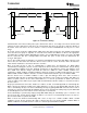
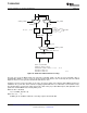
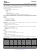
Figure 22. Audio Clock Generation Processing
The part can accept an MCLK input from 512 kHz to 50 MHz, which can then be passed through either a
programmable divider or a PLL, to get the proper internal audio master clock needed by the part. The BCLK
input can also be used to generate the internal audio master clock.
A primary concern is proper operation of the codec at various sample rates with the limited MCLK frequencies
available in the system. This device includes a highly programmable PLL to accommodate such situations easily.
The integrated PLL can generate audio clocks from a wide variety of possible MCLK inputs, with particular focus
paid to the standard MCLK rates already widely used.
When the PLL is disabled,
f
S(ref)
= CLKDIV_IN/(128 × Q)
Where Q = 2, 3, … , 17
CLKDIV_IN can be MCLK or BCLK, selected by register 102, bits D7 – D6.
28 Submit Documentation Feedback Copyright © 2007 – 2008, Texas Instruments Incorporated
Product Folder Link(s): TLV320AIC3105