
Datasheet

H(z) +
N0 ) N1 z
*1
32, 768 * D1 z
*1
(1)
DIGITAL AUDIO PROCESSING FOR RECORD PATH
Digital AudioDataSerialInterface
ADC
+
+
DIN
DOUT
BCLK
WCLK
DINL
DINR
DOUTL
DOUTR
ADC
AGC
AGC
RecordPath
RecordPath
Effects
Effects
SW-D1
SW-D2
SW-D4
SW-D3
Left-Channel
AnalogInputs
Right-Channel
AnalogInputs
PGA
0dB–59.5dB,
0.5-dBSteps
PGA
0dB–59.5dB,
0.5-dBSteps
Volume
Control
Volume
Control
DAC
Powered
Down
DAC
Powered
Down
DAC
L
DAC
R
B0173-01
TLV320AIC3105
www.ti.com
......................................................................................................................................... SLAS513B – FEBRUARY 2007 – REVISED DECEMBER 2008
Programming the left channel is done by writing to page 1, registers 65 – 70, and the right channel is programmed
by writing to page 1, registers 71 – 76. After the coefficients have been loaded, these ADC high-pass filter
coefficients can be selected by writing to page 0, register 107, bits D7 – D6, and the high-pass filter can be
enabled by writing to page 0, register 12, bits D7 – D4.
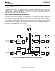
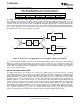
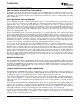
In applications where record only is selected, and DAC is powered down, the playback path signal processing
blocks can be used in the ADC record path. These filtering blocks can support high-pass, low-pass, band-pass or
notch filtering. In this mode, the record only path has switches SW-D1 through SW-D4 closed, and reroutes the
ADC output data through the digital signal processing blocks. Because the DAC digital signal processing blocks
are being re-used, naturally the addresses of these digital filter coefficients are the same as for the DAC digital
processing and are located on page 1, registers 1 – 52. This record only mode is enabled by powering down both
DACs by writing to page 0, register 37, bits D7 – D6 (D7 = D6 = 0). Next, enable the digital filter pathway for the
ADC by writing a 1 to page 0, register 107, bit D3. (Note, this pathway is only enabled if both DACs are powered
down.) This record only path can be seen in Figure 23 .
Figure 23. Record- Only Mode With Digital Processing Path Enabled
Copyright © 2007 – 2008, Texas Instruments Incorporated Submit Documentation Feedback 31
Product Folder Link(s): TLV320AIC3105