
Datasheet

AUTOMATIC GAIN CONTROL (AGC)
TLV320AIC3105
SLAS513B – FEBRUARY 2007 – REVISED DECEMBER 2008 .........................................................................................................................................
www.ti.com
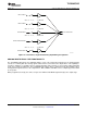
An automatic gain control (AGC) circuit is included with the ADC and can be used to maintain nominally constant
output signal amplitude when recording speech signals (it can be fully disabled if not desired). This circuitry
automatically adjusts the PGA gain as the input signal becomes overly loud or very weak, such as when a
person speaking into a microphone moves closer or farther from the microphone. The AGC algorithm has several
programmable settings, including target gain, attack and decay time constants, noise threshold, and maximum
PGA gain applicable that allow the algorithm to be fine tuned for any particular application. The algorithm uses
the absolute average of the signal (which is the average of the absolute value of the signal) as a measure of the
nominal amplitude of the output signal.
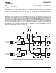
Note that completely independent AGC circuitry is included with each ADC channel with entirely independent
control over the algorithm from one channel to the next. This is attractive in cases where two microphones are
used in a system, but may have different placement in the end equipment and require different dynamic
performance for optimal system operation.
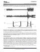
Target level represents the nominal output level at which the AGC attempts to hold the ADC output signal level.
The TLV320AIC3105 allows programming of eight different target levels, which can be programmed from – 5.5
dB to – 24 dB relative to a full-scale signal. Because the device reacts to the signal absolute average and not to
peak levels, it is recommended that the target level be set with enough margin to avoid clipping at the occurrence
of loud sounds.
Attack time determines how quickly the AGC circuitry reduces the PGA gain when the input signal is too loud. It
can be varied from 7 ms to 1,408 ms. The extended right-channel Attack time can be programmed by writing to
page 0, registers 103, and left channel is programmed by writing to page 0, register 105.
Decay time determines how quickly the PGA gain is increased when the input signal is too low. It can be varied
in the range from 0.05 s to 22.4 s. The extended right-channel decay time can be programmed by writing to page
0, register 104, and the left channel is programmed by writing to page 0, register 106.
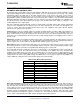
The actual AGC decay time maximum is based on a counter length, so the maximum decay time scales with the
clock setup that is used. The table below shows the relationship of the NADC ratio to the maximum time
available for the AGC decay. In practice, these maximum times are extremely long for audio applications and
should not limit any practical AGC decay time that is needed by the system. (In the TLV320AIC3105, the NDAC
setting must be the same as the NADC setting. The NDAC ratio is set on page 0, register 2. The NDAC is set
equal to NADC by setting the value of bits D7 – D4 equal to that of bits D3 – D0.)
Table 2. AGC Decay Time Restriction
NADC RATIO MAXIMUM DECAY TIME (SECONDS)
1 4
1.5 5.6
2 8
2.5 9.6
3 11.2
3.5 11.2
4 16
4.5 16
5 19.2
5.5 22.4
6 22.4
Noise gate threshold determines the level below which if the input speech average value falls, AGC considers it
as a silence and hence brings down the gain to 0 dB in steps of 0.5 dB every FS and sets the noise threshold
flag. The gain stays at 0 dB unless the input speech signal average rises above the noise threshold setting. This
ensures that noise does not get gained up in the absence of speech. Noise threshold level in the AGC algorithm
is programmable from – 30 dB to – 90 dB relative to full scale. A disable noise gate feature is also available. This
operation includes programmable debounce and hysteresis functionality to avoid the AGC gain from cycling
between high gain and 0 dB when signals are near the noise threshold level. When the noise threshold flag is
set, the status of gain applied by the AGC and the saturation flag should be ignored.
32 Submit Documentation Feedback Copyright © 2007 – 2008, Texas Instruments Incorporated
Product Folder Link(s): TLV320AIC3105