
Datasheet

VCM
VCM
HPLOUT
HPLCOM
HPRCOM
HPROUT
DAC_L2
DAC_R2
LINE2L
LINE2L
LINE2L
LINE2L
LINE2R
LINE2R
LINE2R
LINE2R
PGA_L
PGA_L
PGA_L
PGA_L
DAC_L1
DAC_L1
DAC_L1
DAC_L1
DAC_R1
DAC_R1
DAC_R1
DAC_R1
B0159-02
PGA_R
PGA_R
PGA_R
PGA_R
Volume
Controls,
Mixing
Volume
Controls,
Mixing
Volume
Controls,
Mixing
Volume
Controls,
Mixing
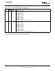
VolumeLevel
0dBto9dB,Mute
VolumeLevel
0dBto9dB,Mute
VolumeLevel
0dBto9dB,Mute
VolumeLevel
0dBto9dB,Mute
TLV320AIC3105
SLAS513B – FEBRUARY 2007 – REVISED DECEMBER 2008 .........................................................................................................................................
www.ti.com
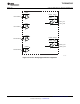
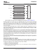
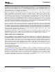
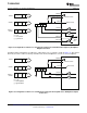
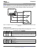
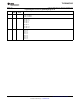
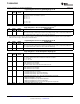
The output stage architecture leading to the high-power output drivers is shown in Figure 31 , with the volume
control and mixing blocks being effectively identical to that shown in Figure 30 . Note that each of these drivers
have a output level control block like those included with the line output drivers, allowing gain adjustment up to 9
dB on the output signal. As in the previous case, this output level adjustment is not intended to be used as a
standard volume control, but instead is included for additional fullscale output signal level control.
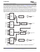
Two of the output drivers, HPROUT and HPLOUT, include a direct connection path for the stereo DAC outputs to
be passed directly to the output drivers and bypass the analog volume controls and mixing networks, using the
DAC_L2/R2 path. As in the line output case, this functionality provides the highest quality DAC playback
performance with reduced power dissipation, but can only be utilized if the DAC output does not need to route to
multiple output drivers simultaneously, and if mixing of the DAC output with other analog signals is not needed.
Figure 31. Architecture of the Output Stage Leading to the High-Power Output Drivers
44 Submit Documentation Feedback Copyright © 2007 – 2008, Texas Instruments Incorporated
Product Folder Link(s): TLV320AIC3105