
Datasheet

TLV320AIC3105
www.ti.com
......................................................................................................................................... SLAS513B – FEBRUARY 2007 – REVISED DECEMBER 2008
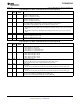
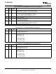
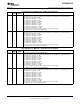
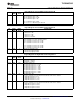
Page 0/Register 8: Audio Serial Data Interface Control Register A
BIT READ/ RESET DESCRIPTION
WRITE VALUE
D7 R/W 0 Bit Clock Directional Control
0: BCLK is an input (slave mode)
1: BCLK is an output (master mode)
D6 R/W 0 Word Clock Directional Control
0: WCLK is an input (slave mode)
1: WCLK is an output (master mode)
D5 R/W 0 Serial Output Data Driver (DOUT) 3-State Control
0: Do not place DOUT in high-impedance state when valid data is not being sent.
1: Place DOUT in high-impedance state when valid data is not being sent.
D4 R/W 0 Bit/ Word Clock Drive Control
0: BCLK/WCLK does not continue to be transmitted when running in master mode if codec is powered
down.
1: BCLK/WCLK continues to be transmitted when running in master mode, even if codec is powered
down.
D3 R/W 0 Reserved. Do not write to this register bit.
D2 R/W 0 3-D Effect Control
0: Disable 3-D digital effect processing
1: Enable 3-D digital effect processing
D1 – D0 R/W 00 Reserved. Write only 00 to these bits.
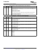
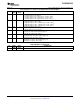
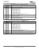
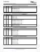
Page 0/Register 9: Audio Serial Data Interface Control Register B
BIT READ/ RESET DESCRIPTION
WRITE VALUE
D7 – D6 R/W 00 Audio Serial Data Interface Transfer Mode
00: Serial data bus uses I
2
S mode
01: Serial data bus uses DSP mode
10: Serial data bus uses right-justified mode
11: Serial data bus uses left-justified mode
D5 – D4 R/W 00 Audio Serial Data Word Length Control
00: Audio data word length = 16 bits
01: Audio data word length = 20 bits
10: Audio data word length = 24 bits
11: Audio data word length = 32 bits
D3 R/W 0 Bit Clock Rate Control
This register only has effect when bit clock is programmed as an output
0: Continuous-transfer mode used to determine master mode bit clock rate
1: 256-clock transfer mode used, resulting in 256 bit clocks per frame
D2 R/W 0 DAC Re-Sync
0: Don ’ t Care
1: Re-sync stereo DAC with codec interface if the group delay changes by more than ± DAC (f
S
/4).
D1 R/W 0 ADC Re-Sync
0: Don ’ t Care
1: Re-sync stereo ADC with codec interface if the group delay changes by more than ± ADC (f
S
/4).
D0 R/W Re-Sync Mute Behavior
0: Re-sync is done without soft-muting the channel (ADC/DAC).
1: Re-sync is done by internally soft-muting the channel (ADC/DAC).
Copyright © 2007 – 2008, Texas Instruments Incorporated Submit Documentation Feedback 51
Product Folder Link(s): TLV320AIC3105