
Datasheet

TLV320AIC3105
SLAS513B – FEBRUARY 2007 – REVISED DECEMBER 2008 .........................................................................................................................................
www.ti.com
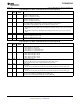
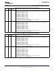
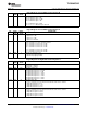
Page 0/Register 10: Audio Serial Data Interface Control Register C
BIT READ/ RESET DESCRIPTION
WRITE VALUE
D7 – D0 R/W 0000 0000 Audio Serial Data Word Offset Control
This register determines where valid data is placed or expected in each frame, by controlling the offset
from beginning of the frame where valid data begins. The offset is measured from the rising edge of word
clock when in DSP mode.
0000 0000: Data offset = 0 bit clocks
0000 0001: Data offset = 1 bit clock
0000 0010: Data offset = 2 bit clocks
…
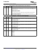
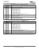
Note: In continuous transfer mode the maximum offset is 17 for I
2
S/LJF/RJF modes and 16 for DSP
mode. In 256-clock mode, the maximum offset is 242 for I
2
S/LJF/RJF and 241 for DSP modes.
1111 1110: Data offset = 254 bit clocks
1111 1111: Data offset = 255 bit clocks
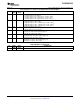
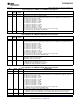
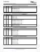
Page 0/Register 11: Audio Codec Overflow Flag Register
BIT READ/ RESET DESCRIPTION
WRITE VALUE
D7 R 0 Left-ADC Overflow Flag
This is a sticky bit, which stays set if an overflow occurs, even if the overflow condition is removed. The
register bit reset to 0 after it is read.
0: No overflow has occurred.
1: An overflow has occurred.
D6 R 0 Right ADC Overflow Flag
This is a sticky bit, which stays set if an overflow occurs, even if the overflow condition is removed. The
register bit reset to 0 after it is read.
0: No overflow has occurred.
1: An overflow has occurred.
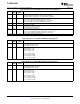
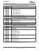
D5 R 0 Left-DAC Overflow Flag
This is a sticky bit, which stays set if an overflow occurs, even if the overflow condition is removed. The
register bit reset to 0 after it is read.
0: No overflow has occurred.
1: An overflow has occurred.
D4 R 0 Right DAC Overflow Flag
This is a sticky bit, which stays set if an overflow occurs, even if the overflow condition is removed. The
register bit reset to 0 after it is read.
0: No overflow has occurred.
1: An overflow has occurred.
D3 – D0 R/W 0001 PLL R Value
0000: R = 16
0001: R = 1
0010: R = 2
0011: R = 3
0100: R = 4
…
1110: R = 14
1111: R = 15
52 Submit Documentation Feedback Copyright © 2007 – 2008, Texas Instruments Incorporated
Product Folder Link(s): TLV320AIC3105