
Datasheet

TLV320AIC3105
SLAS513B – FEBRUARY 2007 – REVISED DECEMBER 2008 .........................................................................................................................................
www.ti.com
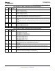
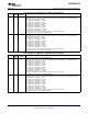
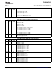
Page 0/Register 19: LINE1L to Left-ADC Control Register
BIT READ/ RESET DESCRIPTION
WRITE VALUE
D7 R/W 0 Reserved
D6 – D3 R/W 1111 LINE1L Input Level Control for Left-ADC PGA Mix
Setting the input level control to a gain below automatically connects LINE1L to the left-ADC PGA mix.
0000: Input level control gain = 0 dB
0001: Input level control gain = – 1.5 dB
0010: Input level control gain = – 3 dB
0011: Input level control gain = – 4.5 dB
0100: Input level control gain = – 6 dB
0101: Input level control gain = – 7.5 dB
0110: Input level control gain = – 9 dB
0111: Input level control gain = – 10.5 dB
1000: Input level control gain = – 12 dB
1001 – 1110: Reserved. Do not write these sequences to these register bits.
1111: LINE1L is not connected to the left-ADC PGA.
D2 R/W 0 Left-ADC Channel Power Control
0: Left-ADC channel is powered down.
1: Left-ADC channel is powered up.
D1 – D0 R/W 00 Left-ADC PGA Soft-Stepping Control
00: Left-ADC PGA soft-stepping at once per f
S
01: Left-ADC PGA soft-stepping at once per two f
S
10 – 11: Left-ADC PGA soft-stepping is disabled.
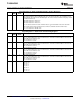
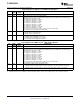
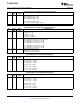
Page 0/Register 20: LINE2L to Left
(1)
-ADC Control Register
BIT READ/ RESET DESCRIPTION
WRITE VALUE
D7 R/W 0 Reserved
D6 – D3 R/W 1111 LINE2L Input Level Control for Left-ADC PGA Mix
Setting the input level control to a gain below automatically connects LINE2L to the left-ADC PGA mix.
0000: Input level control gain = 0 dB
0001: Input level control gain = – 1.5 dB
0010: Input level control gain = – 3 dB
0011: Input level control gain = – 4.5 dB
0100: Input level control gain = – 6 dB
0101: Input level control gain = – 7.5 dB
0110: Input level control gain = – 9 dB
0111: Input level control gain = – 10.5 dB
1000: Input level control gain = – 12 dB
1001 – 1110: Reserved. Do not write these sequences to these register bits.
1111: LINE2L is not connected to the left-ADC PGA.
D2 R/W 0 Left-ADC-Channel Weak Common-Mode Bias Control
0: Left-ADC-channel unselected inputs are not biased weakly to the ADC common-mode voltage.
1: Left-ADC-channel unselected inputs are biased weakly to the ADC common-mode voltage.
D1 – D0 R 00 Reserved. Write only zeros to these register bits
(1) LINE1R SEvsFD control is available for both left and right channels. However, this setting must be same for both the channels.
56 Submit Documentation Feedback Copyright © 2007 – 2008, Texas Instruments Incorporated
Product Folder Link(s): TLV320AIC3105