
Datasheet

TLV320AIC3105
SLAS513B – FEBRUARY 2007 – REVISED DECEMBER 2008 .........................................................................................................................................
www.ti.com
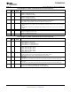
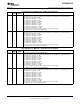
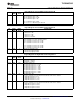
Page 0/Register 24: LINE1L to Right ADC Control Register
BIT READ/ RESET DESCRIPTION
WRITE VALUE
D7 R/W 0 Reserved
D6 – D3 R/W 1111 LINE1L Input Level Control for Right ADC PGA Mix
Setting the input level control to a gain below automatically connects LINE1L to the right ADC PGA mix.
0000: Input level control gain = 0 dB
0001: Input level control gain = – 1.5 dB
0010: Input level control gain = – 3 dB
0011: Input level control gain = – 4.5 dB
0100: Input level control gain = – 6 dB
0101: Input level control gain = – 7.5 dB
0110: Input level control gain = – 9 dB
0111: Input level control gain = – 10.5 dB
1000: Input level control gain = – 12 dB
1001 – 1110: Reserved. Do not write these sequences to these register bits.
1111: LINE1L is not connected to the right ADC PGA.
D2 – D0 R 000 Reserved. Write only zeros to these register bits.
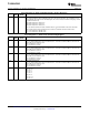
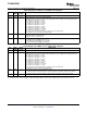
Page 0/Register 25: MICBIAS Control Register
BIT READ/ RESET DESCRIPTION
WRITE VALUE
D7 – D6 R/W 00 MICBIAS Level Control
00: MICBIAS output is powered down.
01: MICBIAS output is powered to 2 V.
10: MICBIAS output is powered to 2.5 V.
11: MICBIAS output is connected to AVDD
D5 – D3 R 000 Reserved. Write only zeros to these bits.
D2 – D0 R XXX Reserved. Write only zeros to these bits.
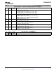
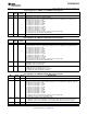
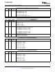
Page 0/Register 26: Left-AGC Control Register A
BIT READ/ RESET DESCRIPTION
WRITE VALUE
D7 R/W 0 Left-AGC Enable
0: Left AGC is disabled.
1: Left AGC is enabled.
D6 – D4 R/W 000 Left-AGC Target Level
000: Left-AGC target level = – 5.5 dB
001: Left-AGC target level = – 8 dB
010: Left-AGC target level = – 10 dB
011: Left-AGC target level = – 12 dB
100: Left-AGC target level = – 14 dB
101: Left-AGC target level = – 17 dB
110: Left-AGC target level = – 20 dB
111: Left-AGC target level = – 24 dB
D3 – D2 R/W 00 Left-AGC Attack Time
These time constants
(1)
are not accurate when double-rate audio mode is enabled.
00: Left-AGC attack time = 8 ms
01: Left-AGC attack time = 11 ms
10: Left-AGC attack time = 16 ms
11: Left-AGC attack time = 20 ms
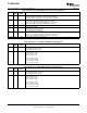
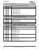
D1 – D0 R/W 00 Left-AGC Decay Time
These time constants
(1)
are not accurate when double-rate audio mode is enabled.
00: Left-AGC decay time = 100 ms
01: Left-AGC decay time = 200 ms
10: Left-AGC decay time = 400 ms
11: Left-AGC decay time = 500 ms
(1) Time constants are valid when DRA is not enabled. The values would change if DRA is enabled.
58 Submit Documentation Feedback Copyright © 2007 – 2008, Texas Instruments Incorporated
Product Folder Link(s): TLV320AIC3105