
Datasheet

TLV320AIC3105
www.ti.com
......................................................................................................................................... SLAS513B – FEBRUARY 2007 – REVISED DECEMBER 2008
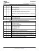
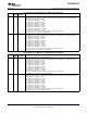
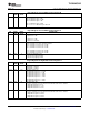
Page 0/Register 27: Left-AGC Control Register B
BIT READ/ RESET DESCRIPTION
WRITE VALUE
D7 – D1 R/W 1111 111 Left-AGC Maximum Gain Allowed
0000 000: Maximum gain = 0 dB
0000 001: Maximum gain = 0.5 dB
0000 010: Maximum gain = 1 dB
…
1110 110: Maximum gain = 59 dB
1110 111 – 1111 111: Maximum gain = 59.5 dB
D0 R/W 0 Reserved. Write only zero to this bit.
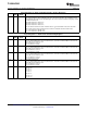
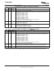
Page 0/Register 28: Left-AGC Control Register C
BIT READ/ RESET DESCRIPTION
WRITE VALUE
D7 – D6 R/W 00 Noise Gate Hysteresis Level Control
00: Hysteresis = 1 dB
01: Hysteresis = 2 dB
10: Hysteresis = 3 dB
11: Hysteresis is disabled
D5 – D1 R/W 00 000 Left-AGC Noise Threshold Control
00 000: Left-AGC noise/silence detection disabled
00 001: Left-AGC noise threshold = – 30 dB
00 010: Left-AGC noise threshold = – 32 dB
00 011: Left-AGC noise threshold = – 34 dB
…
11 101: Left-AGC noise threshold = – 86 dB
11 110: Left-AGC noise threshold = – 88 dB
11 111: Left-AGC noise threshold = – 90 dB
D0 R/W 0 Left-AGC Clip Stepping Control
0: Left-AGC clip stepping disabled
1: Left-AGC clip stepping enabled
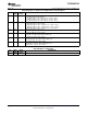
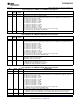
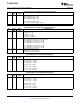
Page 0/Register 29: Right AGC Control Register A
BIT READ/ RESET DESCRIPTION
WRITE VALUE
D7 R/W 0 Right AGC Enable
0: Right AGC is disabled
1: Right AGC is enabled
D6 – D4 R/W 000 Right AGC Target Level
000: Right AGC target level = – 5.5 dB
001: Right AGC target level = – 8 dB
010: Right AGC target level = – 10 dB
011: Right AGC target level = – 12 dB
100: Right AGC target level = – 14 dB
101: Right AGC target level = – 17 dB
110: Right AGC target level = – 20 dB
111: Right AGC target level = – 24 dB
D3 – D2 R/W 00 Right AGC Attack Time
These time constants are not accurate when double-rate audio mode is enabled.
00: Right AGC attack time = 8 ms
01: Right AGC attack time = 11 ms
10: Right AGC attack time = 16 ms
11: Right AGC attack time = 20 ms
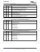
D1 – D0 R/W 00 Right AGC Decay Time
These time constants are not accurate when double-rate audio mode is enabled.
00: Right AGC decay time = 100 ms
01: Right AGC decay time = 200 ms
10: Right AGC decay time = 400 ms
11: Right AGC decay time = 500 ms
Copyright © 2007 – 2008, Texas Instruments Incorporated Submit Documentation Feedback 59
Product Folder Link(s): TLV320AIC3105