
Datasheet


Output Stage Volume Controls
TLV320AIC3105
www.ti.com
......................................................................................................................................... SLAS513B – FEBRUARY 2007 – REVISED DECEMBER 2008
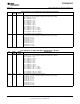
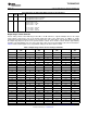
Page 0/Register 44: Right DAC Digital Volume Control Register
BIT READ/ RESET DESCRIPTION
WRITE VALUE
D7 R/W 1 Right DAC Digital Mute
0: The right DAC channel is not muted.
1: The right DAC channel is muted.
D6 – D0 R/W 000 0000 Right DAC Digital Volume Control Setting
000 0000: Gain = 0 dB
000 0001: Gain = – 0.5 dB
000 0010: Gain = – 1 dB
…
111 1101: Gain = – 62.5 dB
111 1110: Gain = – 63 dB
111 1111: Gain = – 63.5 dB
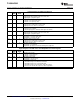
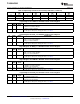
A basic analog volume control with range from 0 dB to – 78 dB and mute is replicated multiple times in the output
stage network, connected to each of the analog signals that route to the output stage. In addition, to enable
completely independent mixing operations to be performed for each output driver, each analog signal coming into
the output stage may have up to seven separate volume controls. These volume controls all have approximately
0.5-dB step programmability over most of the gain range, with steps increasing slightly at the lowest attenuations.
Table 6 lists the detailed gain versus programmed setting for this basic volume control.
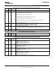
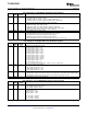
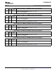
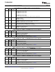
Table 6. Output Stage Volume Control Settings and Gains
Gain Setting Analog Gain Gain Setting Analog Gain Gain Setting Analog Gain Gain Setting Analog Gain
(dB) (dB) (dB) (dB)
0 0 30 – 15 60 – 30.1 90 – 45.2
1 – 0.5 31 – 15.5 61 – 30.6 91 – 45.8
2 – 1 32 – 16 62 – 31.1 92 – 46.2
3 – 1.5 33 – 16.5 63 – 31.6 93 – 46.7
4 – 2 34 – 17 64 – 32.1 94 – 47.4
5 – 2.5 35 – 17.5 65 – 32.6 95 – 47.9
6 – 3 36 – 18 66 – 33.1 96 – 48.2
7 – 3.5 37 – 18.6 67 – 33.6 97 – 48.7
8 – 4 38 – 19.1 68 – 34.1 98 – 49.3
9 – 4.5 39 – 19.6 69 – 34.6 99 – 50
10 – 5 40 – 20.1 70 – 35.1 100 – 50.3
11 – 5.5 41 – 20.6 71 – 35.7 101 – 51
12 – 6 42 – 21.1 72 – 36.1 102 – 51.4
13 – 6.5 43 – 21.6 73 – 36.7 103 – 51.8
14 – 7 44 – 22.1 74 – 37.1 104 – 52.2
15 – 7.5 45 – 22.6 75 – 37.7 105 – 52.7
16 – 8 46 – 23.1 76 – 38.2 106 – 53.7
17 – 8.5 47 – 23.6 77 – 38.7 107 – 54.2
18 – 9 48 – 24.1 78 – 39.2 108 – 55.3
19 – 9.5 49 – 24.6 79 – 39.7 109 – 56.7
20 – 10 50 – 25.1 80 – 40.2 110 – 58.3
21 – 10.5 51 – 25.6 81 – 40.7 111 – 60.2
22 – 11 52 – 26.1 82 – 41.2 112 – 62.7
23 – 11.5 53 – 26.6 83 – 41.7 113 – 64.3
24 – 12 54 – 27.1 84 – 42.2 114 – 66.2
25 – 12.5 55 – 27.6 85 – 42.7 115 – 68.7
26 – 13 56 – 28.1 86 – 43.2 116 – 72.2
Copyright © 2007 – 2008, Texas Instruments Incorporated Submit Documentation Feedback 65
Product Folder Link(s): TLV320AIC3105