
Datasheet
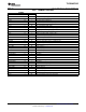
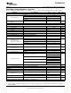

ELECTRICAL CHARACTERISTICS
TLV320AIC3105
www.ti.com
......................................................................................................................................... SLAS513B – FEBRUARY 2007 – REVISED DECEMBER 2008
At 25 ° C, AVDD_DAC, DRVDD, IOVDD = 3.3 V, DVDD = 1.8 V, f
S
= 48 kHz, 16-bit audio data (unless otherwise noted)
PARAMETER TEST CONDITIONS MIN TYP MAX UNIT
AUDIO ADC
Input signal level (0 dB) Single-ended input 0.707 V
RMS
f
S
= 48 ksps, 0 dB PGA gain, inputs ac-shorted to ground,
Signal-to-noise ratio
(1) (2)
80 92 dB
A-weighted
f
S
= 48 ksps; 0-dB PGA gain – 60-dB full-scale, 1-kHz input
Dynamic range
(1) (2)
93 dB
signal
f
S
= 48 ksps; 0-dB PGA gain; 1-kHz, – 2-dB full-scale input
THD Total harmonic distortion – 89 – 75 dB
signal
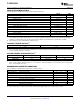
217-Hz signal applied to DRVDD 55
PSRR Power-supply rejection ratio dB
1-kHz signal applied to DRVDD 44
Input channel separation 1-kHz, – 2 dB full-scale signal, MIC1L to MIC1R – 71 dB
f
S
= 48 ksps, 0 dB PGA gain, – 2 dB full-scale 1-kHz input
Gain error 0.82 dB
signal
ADC programmable gain
1-kHz input tone 59.5 dB
amplifier maximum gain
ADC programmable gain
0.5 dB
amplifier step size
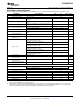
MIC1L/MIC1R inputs routed to single ADC
20
Input multiplex attenuation = 0 dB
MIC1L/MIC1R inputs routed to single ADC
80
Input multiplex attenuation = 12 dB
MIC2L/MIC2R inputs routed to single ADC
20
Input multiplex attenuation = 0 dB
Input resistance k Ω
MIC2L/MIC2R inputs routed to single ADC
80
Input multiplex attenuation = 12 dB
MIC3L/MIC3R inputs routed to single ADC
20
Input multiplex attenuation = 0 dB
MIC3L/MIC3R inputs routed to single ADC
80
Input multiplex attenuation = 12 dB
Input capacitance MIC1/LINE1 inputs 10 pF
Input level control minimum
0 dB
attenuation setting
Input level control maximum
12 dB
attenuation setting
Input level control attenuation
1.5 dB
step size
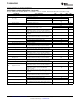
ANALOG PASSTHROUGH MODE
MIC1/LIN1 to LINEOUT, Rds ON 330
Input-to-output switch resistance Ω
MIC2/LIN2 to LINEOUT, Rds ON 330
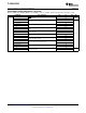
ADC DIGITAL DECIMATION FILTER, f
S
= 48 kHz
Filter gain from 0 to 0.39 f
S
± 0.1 dB
Filter gain at 0.4125 f
S
– 0.25 dB
Filter gain at 0.45 f
S
– 3 dB
Filter gain at 0.5 f
S
– 17.5 dB
Filter gain from 0.55 f
S
to 64 f
S
– 75 dB
Filter group delay 17/f
S
s
(1) Ratio of output level with 1-kHz full-scale sine-wave input, to the output level with the inputs short-circuited, measured A-weighted over a
20-Hz to 20-kHz bandwidth using an audio analyzer.
(2) All performance measurements done with 20-kHz low-pass filter and, where noted, A-weighted filter. Failure to use such a filter may
result in higher THD+N and lower SNR and dynamic range readings than shown in the Electrical Characteristics. The low-pass filter
removes out-of-band noise, which, although not audible, may affect dynamic specification values.
Copyright © 2007 – 2008, Texas Instruments Incorporated Submit Documentation Feedback 7
Product Folder Link(s): TLV320AIC3105