Using the TLV700xxEVM-503 User's Guide Literature Number: SLUU391 December 2009
User's Guide SLUU391 – December 2009 TLV700xxEVM-503 This user’s guide describes the characteristics, operation, and use of the TLV700xxEVM-503 evaluation module (EVM). This EVM demonstrates the Texas Instruments TLV700xx a low dropout (LDO) linear regulator that is capable of 200 mA at both fixed and adjustable output voltage levels. This user’s guide includes setup instructions, a schematic diagram, thermal guidelines, a bill of materials, and printed-circuit board layout drawings for the EVM.
Operation www.ti.com 2.1.4 J4 –GND This is the return connection for the output. 2.1.5 JP1 –ENABLE This jumper enables or disables the regulator. Connecting the shorting jumper between pin 1 and pin 2 (ENABLE and VIN) enables the converter. Connecting the shorting jumper between pin 2 and pin 3 (ENABLE and GND) disables the converter. Never leave this pin floating. 2.
Thermal Guidelines 4 www.ti.com Thermal Guidelines This section provides guidelines for the thermal management of the TLV700xxEVM-503 board. 4.1 Thermal Considerations Thermal management is a key component of design of any power converter and is especially important when the power dissipation in the LDO is high.
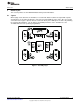
Board Layout www.ti.com 5 Board Layout This section provides the TLV700xxEVM-503 board layout and illustrations 5.1 Layout When laying out the board for the TLV700xx, TI recommends that the board be designed with separate ground planes for Vin and Vout which are only connected at the GND pin of the device. Also, the ground connection for the bypass capacitor must be connected directly to the GND pin of the device.
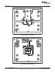
Board Layout www.ti.com Figure 2. Top Layer Routing Figure 3.
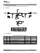
Schematic and List of Materials www.ti.com 6 Schematic and List of Materials This section provides the TLV700xxEVM-503 schematic and List of Materials. 6.1 Schematic Figure 4. TLV700xxEVM-503 Schematic 6.2 List of Materials Table 1. TLV700xxEVM-503 List of Materials COUNT REF DES DESCRIPTION PART NUMBER MFR 2 C1, C2 Capacitor, ceramic, 25 V, X5R, 20%, 1 µF, 805 STD STD 4 J1, J2, J3, J4 Header, 2 pin, 100-mil spacing, 0.
EVALUATION BOARD/KIT IMPORTANT NOTICE Texas Instruments (TI) provides the enclosed product(s) under the following conditions: This evaluation board/kit is intended for use for ENGINEERING DEVELOPMENT, DEMONSTRATION, OR EVALUATION PURPOSES ONLY and is not considered by TI to be a finished end-product fit for general consumer use. Persons handling the product(s) must have electronics training and observe good engineering practice standards.
IMPORTANT NOTICE Texas Instruments Incorporated and its subsidiaries (TI) reserve the right to make corrections, modifications, enhancements, improvements, and other changes to its products and services at any time and to discontinue any product or service without notice. Customers should obtain the latest relevant information before placing orders and should verify that such information is current and complete.