
Datasheet

User's Guide
SLVU553–October 2011
TLV71733PEVM-072 Evaluation Module
This user’s guide describes operational use of the TLV71733PEVM-072 evaluation module as a reference
design for engineering demonstration and evaluation of the TLV717xxP, low-dropout linear regulator.
Included in this user’s guide are setup instructions, a schematic diagram, layout and thermal guidelines, a
bill of materials, and test results.
Contents
1 Introduction .................................................................................................................. 2
2 Setup ......................................................................................................................... 2
2.1 Input/Output Connectors and Jumper Descriptions ........................................................... 2
2.2 Equipment Setup ................................................................................................... 2
3 Operation ..................................................................................................................... 2
4 Test Results ................................................................................................................. 3
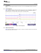
4.1 Turnon Sequence .................................................................................................. 3
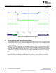
4.2 Output Load Transient ............................................................................................. 3
5 Thermal Guidelines and Layout Recommendations ................................................................... 4
6 Board Layout ................................................................................................................ 5
7 Schematic and Bill of Materials ........................................................................................... 6
7.1 Schematic ........................................................................................................... 6
7.2 Bill of Materials ..................................................................................................... 6
List of Figures
1 Turnon Sequence ........................................................................................................... 3
2 Load Step and Transient Response...................................................................................... 4
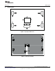
3 Top-Layer Silkscreen ....................................................................................................... 5
4 Top-Layer Routing .......................................................................................................... 5
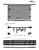
5 Bottom-Layer Routing ...................................................................................................... 6
6 TLV71733PEVM-072 Schematic.......................................................................................... 6
List of Tables
1 TLV71733PEVM-072 Bill of Materials.................................................................................... 6
1
SLVU553–October 2011 TLV71733PEVM-072 Evaluation Module
Submit Documentation Feedback
Copyright © 2011, Texas Instruments Incorporated