TLVH431, TLVH431A, TLVH431B TLVH432, TLVH432A, TLVH432B www.ti.com....................................................................................................................................... SLVS555I – NOVEMBER 2004 – REVISED SEPTEMBER 2009 LOW-VOLTAGE ADJUSTABLE PRECISION SHUNT REGULATORS Check for Samples: TLVH431 TLVH431A TLVH431B TLVH432 TLVH432A TLVH432B FEATURES 1 • • • • • Low-Voltage Operation: Down to 1.24 V Reference Voltage Tolerances at 25°C – 0.
TLVH431, TLVH431A, TLVH431B TLVH432, TLVH432A, TLVH432B SLVS555I – NOVEMBER 2004 – REVISED SEPTEMBER 2009....................................................................................................................................... www.ti.com DESCRIPTION/ORDERING INFORMATION The TLVH431 and TLVH432 are low-voltage 3-terminal adjustable voltage references, with specified thermal stability over applicable industrial and commercial temperature ranges.
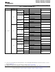
TLVH431, TLVH431A, TLVH431B TLVH432, TLVH432A, TLVH432B www.ti.com....................................................................................................................................... SLVS555I – NOVEMBER 2004 – REVISED SEPTEMBER 2009 Table 1. ORDERING INFORMATION (1) TA VREF TOLERANCE PACKAGE SC-70 – DCK SOT-23-5 – DBV (2) Reel of 3000 TLVH431BCDCKR Reel of 250 TLVH431BCDCKT Reel of 3000 TLVH431BCDBVR Reel of 250 TLVH431BCDBVT Reel of 3000 0.
TLVH431, TLVH431A, TLVH431B TLVH432, TLVH432A, TLVH432B SLVS555I – NOVEMBER 2004 – REVISED SEPTEMBER 2009....................................................................................................................................... www.ti.com Table 1.
TLVH431, TLVH431A, TLVH431B TLVH432, TLVH432A, TLVH432B www.ti.com....................................................................................................................................... SLVS555I – NOVEMBER 2004 – REVISED SEPTEMBER 2009 Table 1.
TLVH431, TLVH431A, TLVH431B TLVH432, TLVH432A, TLVH432B SLVS555I – NOVEMBER 2004 – REVISED SEPTEMBER 2009....................................................................................................................................... www.ti.com LOGIC BLOCK DIAGRAM CATHODE REF + − VREF = 1.
TLVH431, TLVH431A, TLVH431B TLVH432, TLVH432A, TLVH432B www.ti.com.......................................................................................................................................
TLVH431, TLVH431A, TLVH431B TLVH432, TLVH432A, TLVH432B SLVS555I – NOVEMBER 2004 – REVISED SEPTEMBER 2009....................................................................................................................................... www.ti.
TLVH431, TLVH431A, TLVH431B TLVH432, TLVH432A, TLVH432B www.ti.com....................................................................................................................................... SLVS555I – NOVEMBER 2004 – REVISED SEPTEMBER 2009 PARAMETER MEASUREMENT INFORMATION Input VO IK VREF Figure 1. Test Circuit for VKA = VREF, VO = VKA = VREF Input VO IK R1 R2 Iref VREF Figure 2. Test Circuit for VKA > VREF, VO = VKA = VREF × (1 + R1/R2) + Iref × R1 Input VO IK(off) Figure 3.
TLVH431, TLVH431A, TLVH431B TLVH432, TLVH432A, TLVH432B SLVS555I – NOVEMBER 2004 – REVISED SEPTEMBER 2009....................................................................................................................................... www.ti.com PARAMETER MEASUREMENT INFORMATION (continued) REFERENCE VOLTAGE vs JUNCTION TEMPERATURE 1.254 IK = 10 mA V ref − Reference Voltage − V 1.252 1.250 1.248 1.246 1.244 1.242 1.240 1.
TLVH431, TLVH431A, TLVH431B TLVH432, TLVH432A, TLVH432B www.ti.com....................................................................................................................................... SLVS555I – NOVEMBER 2004 – REVISED SEPTEMBER 2009 PARAMETER MEASUREMENT INFORMATION (continued) CATHODE CURRENT vs CATHODE VOLTAGE 70 VKA = VREF TA = 25°C I K − Cathode Current − mA 10 5 0 −5 −10 −15 −1 −0.5 0 0.5 1 VKA − Cathode Voltage − V 1.5 Figure 6.
TLVH431, TLVH431A, TLVH431B TLVH432, TLVH432A, TLVH432B SLVS555I – NOVEMBER 2004 – REVISED SEPTEMBER 2009....................................................................................................................................... www.ti.
TLVH431, TLVH431A, TLVH431B TLVH432, TLVH432A, TLVH432B www.ti.com....................................................................................................................................... SLVS555I – NOVEMBER 2004 – REVISED SEPTEMBER 2009 PARAMETER MEASUREMENT INFORMATION (continued) Operation of the device at these or any other conditions beyond those indicated under recommended operating conditions is not implied.
TLVH431, TLVH431A, TLVH431B TLVH432, TLVH432A, TLVH432B SLVS555I – NOVEMBER 2004 – REVISED SEPTEMBER 2009....................................................................................................................................... www.ti.
TLVH431, TLVH431A, TLVH431B TLVH432, TLVH432A, TLVH432B www.ti.com....................................................................................................................................... SLVS555I – NOVEMBER 2004 – REVISED SEPTEMBER 2009 PARAMETER MEASUREMENT INFORMATION (continued) EQUIVALENT INPUT NOISE VOLTAGE OVER A 10-S PERIOD Vn − Equivalent Input Noise Voltage − µ V 10 f = 0.
TLVH431, TLVH431A, TLVH431B TLVH432, TLVH432A, TLVH432B SLVS555I – NOVEMBER 2004 – REVISED SEPTEMBER 2009....................................................................................................................................... www.ti.com PARAMETER MEASUREMENT INFORMATION (continued) 0° 80 IK = 10 mA TA = 25°C 70 36° 60 72° 50 108° 40 144° 30 180° Phase Shift A V − Small-Signal Voltage Gain/Phase Margin − dB SMALL-SIGNAL VOLTAGE GAIN /PHASE MARGIN vs FREQUENCY Output IK 6.
TLVH431, TLVH431A, TLVH431B TLVH432, TLVH432A, TLVH432B www.ti.com....................................................................................................................................... SLVS555I – NOVEMBER 2004 – REVISED SEPTEMBER 2009 PARAMETER MEASUREMENT INFORMATION (continued) PULSE RESPONSE 1 3.5 3 Input and Output Voltage − V R = 18 kΩ TA = 25°C Input 18 kΩ Output 2.5 Ik 2 1.5 Pulse Generator f = 100 kHz Output 50 Ω 1 GND 0.5 0 TEST CIRCUIT FOR PULSE RESPONSE 1 −0.
TLVH431, TLVH431A, TLVH431B TLVH432, TLVH432A, TLVH432B SLVS555I – NOVEMBER 2004 – REVISED SEPTEMBER 2009....................................................................................................................................... www.ti.com PARAMETER MEASUREMENT INFORMATION (continued) 30 kW IK 50 W 100 µF I2 CL I1 Figure 17. Phase Margin Test Circuit IK Figure 18.
TLVH431, TLVH431A, TLVH431B TLVH432, TLVH432A, TLVH432B www.ti.com....................................................................................................................................... SLVS555I – NOVEMBER 2004 – REVISED SEPTEMBER 2009 PARAMETER MEASUREMENT INFORMATION (continued) IK Figure 19. IK Figure 20.
TLVH431, TLVH431A, TLVH431B TLVH432, TLVH432A, TLVH432B SLVS555I – NOVEMBER 2004 – REVISED SEPTEMBER 2009....................................................................................................................................... www.ti.com APPLICATION INFORMATION ∼ VI 120 V − P + ∼ VO 3.3 V P P Gate Drive VCC Controller VFB TLVH431 Current Sense GND P P P P Figure 21.
PACKAGE OPTION ADDENDUM www.ti.
PACKAGE OPTION ADDENDUM www.ti.
PACKAGE OPTION ADDENDUM www.ti.
PACKAGE OPTION ADDENDUM www.ti.
PACKAGE OPTION ADDENDUM www.ti.
PACKAGE OPTION ADDENDUM www.ti.
PACKAGE OPTION ADDENDUM www.ti.
PACKAGE OPTION ADDENDUM www.ti.
PACKAGE OPTION ADDENDUM www.ti.
PACKAGE OPTION ADDENDUM www.ti.
PACKAGE OPTION ADDENDUM www.ti.
PACKAGE OPTION ADDENDUM www.ti.
PACKAGE OPTION ADDENDUM www.ti.
PACKAGE OPTION ADDENDUM www.ti.
PACKAGE OPTION ADDENDUM www.ti.
PACKAGE MATERIALS INFORMATION www.ti.com 5-Oct-2013 TAPE AND REEL INFORMATION *All dimensions are nominal Device Package Package Pins Type Drawing SPQ Reel Reel A0 Diameter Width (mm) (mm) W1 (mm) B0 (mm) K0 (mm) P1 (mm) TLVH431ACDBVR SOT-23 DBV 5 3000 178.0 9.0 3.17 1.37 4.0 8.0 Q3 TLVH431ACDBVR SOT-23 DBV 5 3000 179.0 8.4 3.2 TLVH431ACDBVT SOT-23 DBV 5 250 178.0 9.0 3.23 3.2 1.4 4.0 8.0 Q3 3.17 1.37 4.0 8.0 TLVH431ACDBZR SOT-23 DBZ 3 3000 180.0 8.4 3.
PACKAGE MATERIALS INFORMATION www.ti.com 5-Oct-2013 Device Package Package Pins Type Drawing SPQ Reel Reel A0 Diameter Width (mm) (mm) W1 (mm) B0 (mm) K0 (mm) P1 (mm) W Pin1 (mm) Quadrant TLVH431AQDBZT SOT-23 DBZ 3 250 179.0 8.4 3.15 2.95 1.22 4.0 8.0 Q3 TLVH431AQDCKR SC70 DCK 6 3000 179.0 8.4 2.2 2.5 1.2 4.0 8.0 Q3 TLVH431AQDCKT SC70 DCK 6 250 179.0 8.4 2.2 2.5 1.2 4.0 8.0 Q3 TLVH431AQPK SOT-89 PK 3 1000 180.0 12.4 4.91 4.52 1.9 8.0 12.
PACKAGE MATERIALS INFORMATION www.ti.com 5-Oct-2013 Device Package Package Pins Type Drawing SPQ Reel Reel A0 Diameter Width (mm) (mm) W1 (mm) B0 (mm) K0 (mm) P1 (mm) W Pin1 (mm) Quadrant TLVH431QDCKR SC70 DCK 6 3000 179.0 8.4 2.2 2.5 1.2 4.0 8.0 Q3 TLVH431QDCKT SC70 DCK 6 250 179.0 8.4 2.2 2.5 1.2 4.0 8.0 Q3 TLVH431QPK SOT-89 PK 3 1000 180.0 12.4 4.91 4.52 1.9 8.0 12.0 Q3 TLVH432ACDBZR SOT-23 DBZ 3 3000 179.0 8.4 3.15 2.95 1.22 4.0 8.
PACKAGE MATERIALS INFORMATION www.ti.com 5-Oct-2013 *All dimensions are nominal Device Package Type Package Drawing Pins SPQ Length (mm) Width (mm) Height (mm) TLVH431ACDBVR SOT-23 DBV 5 3000 180.0 180.0 18.0 TLVH431ACDBVR SOT-23 DBV 5 3000 203.0 203.0 35.0 TLVH431ACDBVT SOT-23 DBV 5 250 180.0 180.0 18.0 TLVH431ACDBZR SOT-23 DBZ 3 3000 202.0 201.0 28.0 TLVH431ACDBZT SOT-23 DBZ 3 250 203.0 203.0 35.0 TLVH431ACDCKR SC70 DCK 6 3000 203.0 203.0 35.
PACKAGE MATERIALS INFORMATION www.ti.com 5-Oct-2013 Device Package Type Package Drawing Pins SPQ Length (mm) Width (mm) Height (mm) TLVH431AQDCKT SC70 DCK 6 250 203.0 203.0 35.0 TLVH431AQPK SOT-89 PK 3 1000 340.0 340.0 38.0 TLVH431BCDBVR SOT-23 DBV 5 3000 203.0 203.0 35.0 TLVH431BCDBVT SOT-23 DBV 5 250 203.0 203.0 35.0 TLVH431BCDBZR SOT-23 DBZ 3 3000 203.0 203.0 35.0 TLVH431BCDBZT SOT-23 DBZ 3 250 203.0 203.0 35.
PACKAGE MATERIALS INFORMATION www.ti.com 5-Oct-2013 Device Package Type Package Drawing Pins SPQ Length (mm) Width (mm) Height (mm) TLVH432ACDBZR SOT-23 DBZ 3 3000 203.0 203.0 35.0 TLVH432ACDBZT SOT-23 DBZ 3 250 203.0 203.0 35.0 TLVH432AIDBZR SOT-23 DBZ 3 3000 202.0 201.0 28.0 TLVH432AIPK SOT-89 PK 3 1000 340.0 340.0 38.0 TLVH432AQDBZR SOT-23 DBZ 3 3000 203.0 203.0 35.0 TLVH432AQDBZT SOT-23 DBZ 3 250 203.0 203.0 35.
IMPORTANT NOTICE Texas Instruments Incorporated and its subsidiaries (TI) reserve the right to make corrections, enhancements, improvements and other changes to its semiconductor products and services per JESD46, latest issue, and to discontinue any product or service per JESD48, latest issue. Buyers should obtain the latest relevant information before placing orders and should verify that such information is current and complete.